Liquid crystal device
A technology of liquid crystal devices and liquid crystal components, which can be used in instruments, static indicators, nonlinear optics, etc., and can solve problems such as complexity
- Summary
- Abstract
- Description
- Claims
- Application Information
AI Technical Summary
Problems solved by technology
Method used
Image
Examples
Embodiment approach -1
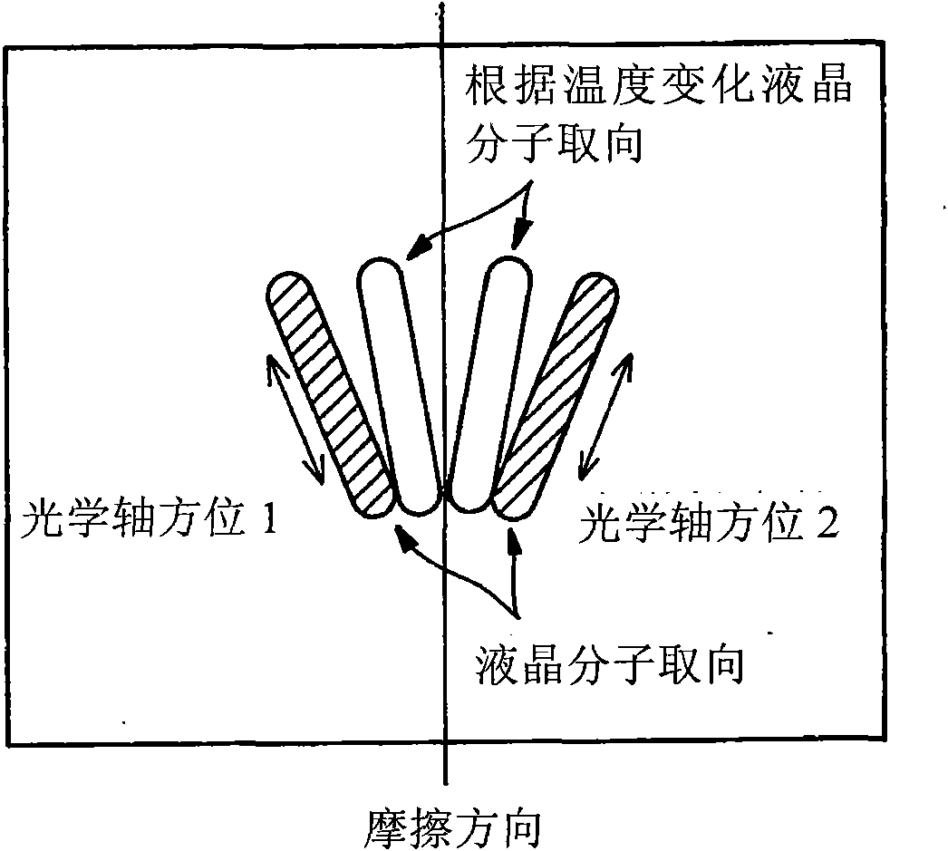
[0086] In one embodiment of the present invention, the liquid crystal device includes at least a pair of polarizers whose transmission axes are perpendicular to each other, a liquid crystal element arranged between the pair of polarizers, and a voltage applying device for applying a voltage to the liquid crystal element. The liquid crystal element includes at least a pair of substrates and a liquid crystal material arranged between the pair of substrates, and is a liquid crystal element in which the liquid crystal material can rotate the orientation of the optical axis according to the magnitude and / or direction of an applied electric field. In addition, the voltage applying means is a voltage applying means capable of controlling the voltage applied by the voltage applying means to the liquid crystal element according to the orientation of the liquid crystal molecules in the liquid crystal material.
Embodiment approach -2
[0088] In another embodiment of the present invention, the liquid crystal device includes a pair of polarizing elements whose transmission axes cross each other, the liquid crystal element disposed between the pair of polarizing elements, and an angle adjusting device for adjusting the angle between the liquid crystal element and the polarizing element. The liquid crystal element includes at least a pair of substrates and a liquid crystal material arranged between the pair of substrates, and is a liquid crystal element in which the liquid crystal material can rotate the orientation of the optical axis according to the magnitude and / or direction of an applied electric field. In addition, the above-mentioned angle adjusting device is an angle adjusting device capable of adjusting the angle between the liquid crystal element and the polarizing element according to the orientation of the liquid crystal molecules in the liquid crystal material.
[0089] (PSS-LCD)
[0090] In the pr...
Embodiment approach 1
[0200] In the present invention, a PSS-LCD having the following configuration can also be used.
[0201] PSS-LCD, which at least contains a pair of substrates, a liquid crystal material arranged between the pair of substrates, and a pair of polarizing films arranged outside the pair of substrates; one of the pair of polarizing films has the function of matching the liquid crystal material The direction of the orientation treatment is parallel or substantially parallel to the initial molecular orientation, and the other of the pair of polarizing films has a polarized light absorption direction perpendicular to the orientation treatment of the liquid crystal material; and,
[0202] A liquid crystal cell exhibits an extinction angle in the absence of an externally applied voltage.
[0203] This form of liquid crystal display, in addition to the above features, has the advantage that its extinction level is substantially independent of temperature. In this form, the temperature d...
PUM
| Property | Measurement | Unit |
|---|---|---|
| particle diameter | aaaaa | aaaaa |
Abstract
Description
Claims
Application Information
 - R&D
- Intellectual Property
- Life Sciences
- Materials
- Tech Scout
- Unparalleled Data Quality
- Higher Quality Content
- 60% Fewer Hallucinations
Browse by: Latest US Patents, China's latest patents, Technical Efficacy Thesaurus, Application Domain, Technology Topic, Popular Technical Reports.
© 2025 PatSnap. All rights reserved.Legal|Privacy policy|Modern Slavery Act Transparency Statement|Sitemap|About US| Contact US: help@patsnap.com


