Rotary-vane multifunctional multi-purpose valve

A multi-functional and multi-purpose technology, applied in the field of invention, can solve problems such as single function, and achieve the effects of large circulation, high pressure resistance and increased cost

Inactive Publication Date: 2009-12-23
中山市九虹机器人科技有限公司
View PDF0 Cites 29 Cited by
  • Summary
  • Abstract
  • Description
  • Claims
  • Application Information

AI Technical Summary

Problems solved by technology

The function of the valve is single, and it can only complete the opening of one channel → adjust from small to large

Method used


Image

  • Rotary-vane multifunctional multi-purpose valve
  • Rotary-vane multifunctional multi-purpose valve
  • Rotary-vane multifunctional multi-purpose valve

Examples


Embodiment 1

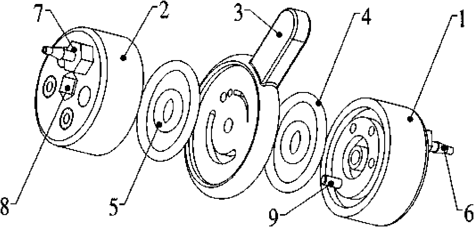
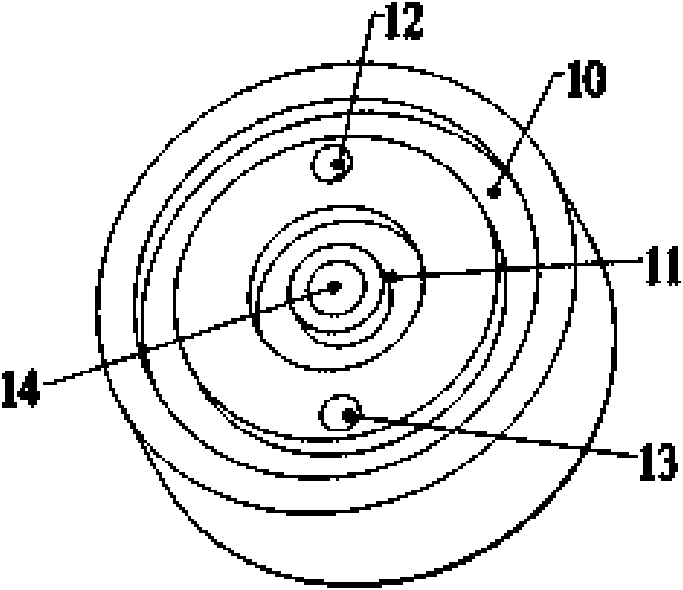
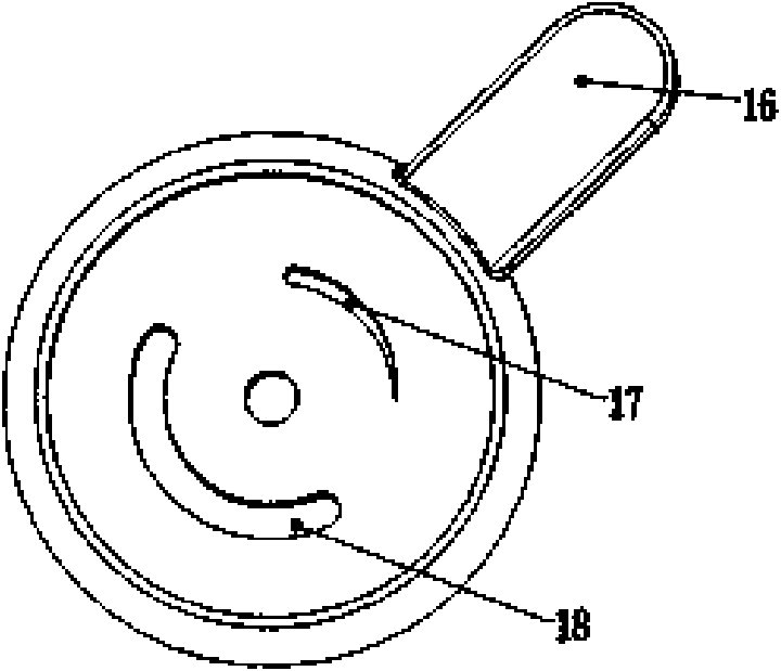
[0031] A rotary vane multifunctional multipurpose valve, such as figure 1 As shown, there are two circular valve bodies, that is, the first valve body 1 (inlet), the second valve body 2 (outlet), valve plate (rotary plate) 3, large circular sealing ring 4, small circular The sealing ring 5, the water inlet nozzle 6, the water outlet nozzle 7, the fastening screw 8 and the positioning pin 9 are assembled together. Wherein, on the opposite surfaces of the first valve body 1 and the second valve body 2, the center is a fastening hole 14, and two circles of different sizes for installing the large circular sealing ring 4 and the small circular sealing ring 5 are arranged concentrically. There is a liquid-inlet hole 12 and a positioning pin hole 13 at the position between the two circular sealing rings, and the valve plate 3 is provided with an arc-shaped groove 18 for passing the positioning pin 9, see figure 2 and image 3 .

[0032] On the other side of the first valve body ...

specific Embodiment 2

[0035] On the basis of Embodiment 1, the right liquid outlet hole on the second valve body 2 is connected, that is, two adjacent fluid passages are opened, see Figure 7 As shown, the distance between the openings of two adjacent fluid passages is less than the length of the flow regulating groove, and an adjustable bypass can be formed by rotating the valve plate 3 . When the valve plate 3 is rotated to the maximum open position, the valve can be used as a three-way.

Embodiment 3

[0037] On the basis of Embodiment 1, close the plug of the middle fluid passage on the second valve body 2, open the left and right fluid passages on the second valve body 2, that is, open two non-adjacent fluid passages, and the distance between the mutually spaced openings is greater than the length of the flow regulating groove, see Figure 8 As shown, when the valve plate 3 is in the Figure 6 When rotating between the positions shown, the switching between the fluid passage on the first valve body 1 and the two different passages on the second valve body 2 can be completed, from Figure 8 The connected state on the left becomes the connected state on the right.


PUM


Abstract

The invention discloses a rotary-vane multifunctional multi-purpose valve which comprises valve bodies and a valve plate arranged between the valve bodies, wherein the valve body is provided with a fluid passage. The valve is characterized in that the rotary-vane multifunctional multi-purpose valve comprises a first valve body and a second valve body which are arranged together; each valve body is provided with at least one fluid passage which corresponds to openings on the opposite surfaces of the first valve body and the second valve body; a shaft is arranged between the first valve body and the second valve body; the valve plates are arranged on the shaft and can rotate around the shaft; and a flow regulation groove with gradually changed width is arranged on the valve plate and can be rotated to the position of the opening on the fluid passage of the valve body. The rotary-vane multifunctional multi-purpose valve can realize the switching among single passage flow regulation, single passage adjustable bypass, a tee joint and a four-way joint, the switching between two tee joints and switch between two four-way joints and the like through the rotating positions of the regulation valve plate.

Description

technical field [0001] The invention relates to inventions, in particular to a rotary vane multi-functional multi-purpose valve capable of realizing multi-channel switching and flow regulation. Background technique [0002] Existing valves generally include disc-shaped, spherical globe valves, needle-shaped flow regulating valves, piston-type flow regulating valves, and the like. Its principle is to change the gap with the passage by rotating the disc, sphere, needle-shaped cone, and piston, so as to achieve the purpose of opening, closing, and flow adjustment. These valves can meet the requirements of pressure resistance and temperature resistance for valves in daily life and industry. Usually the diameter of the valve is large; most of them are made of metal. The function of the valve is single, and it can only complete the opening of one passage → the adjustment from small to large. To realize multiple functions, such as: bypass adjustment, several channel switching, m...

Claims


Application Information

Patent Timeline
Patent Type & Authority Applications(China)
IPC IPC(8): F16K3/08F16K3/34F16K11/074
Inventor 林波
Owner 中山市九虹机器人科技有限公司
Why Eureka
Try Eureka