
Method for measuring optical three-dimensional contour of space coding

A three-dimensional contour and space encoding technology, applied in the field of optical three-dimensional contour measurement of space encoding, can solve the problems of the influence of noise points of the encoding pattern, decoding errors, and inability to reflect the resolution, so as to solve the contradiction between speed and accuracy and improve the accuracy. and efficiency

Inactive Publication Date: 2009-12-23
XI AN JIAOTONG UNIV
View PDF0 Cites 20 Cited by
  • Summary
  • Abstract
  • Description
  • Claims
  • Application Information

AI Technical Summary

Problems solved by technology

Coding can be divided into spatial coding and time coding. The spatial coding method can obtain the depth image of the measured object with only one projection, which is suitable for dynamic measurement, but the resolution cannot meet the requirements at present, and the coding pattern is easily affected by the different surface characteristics of the scene. The influence of the generated noise points causes decoding errors
Binary coding is often used for time coding to combine multiple different projection pattern coding sequences for decoding, and the decoding error rate is low, but the method requires that the projection space position remains unchanged and multiple projections are performed, so the measurement speed is affected
In the multi-light knife coding method, there is a pair of contradictory unity of light knife fringe spacing and light knife pattern recognition. The smaller the fringe spacing, the higher the resolution in theory, but it makes the light knife pattern recognition more and more difficult. Theoretical The above resolution cannot be reflected, thus greatly limiting the measurement accuracy
[0004] In addition, the encoding speed is an important aspect that limits the measurement speed
Time coding projects the prefabricated projection patterns onto the surface of the object to be measured in a certain order. The more the number of projections, the longer the encoding process and the lower the measurement speed.

Method used


Image

  • Method for measuring optical three-dimensional contour of space coding
  • Method for measuring optical three-dimensional contour of space coding
  • Method for measuring optical three-dimensional contour of space coding

Examples


Embodiment Construction

[0021] The present invention will be described in further detail below in conjunction with the accompanying drawings.

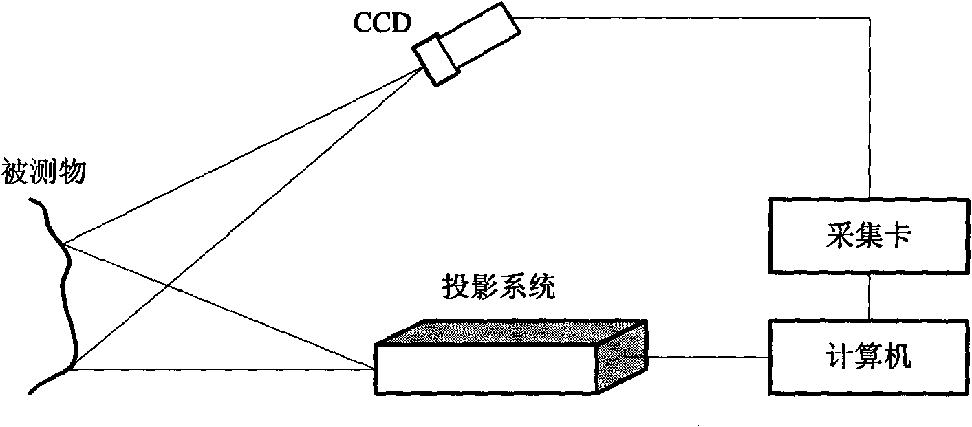
[0022] see figure 1 , is the principle diagram of spatially encoded 3D contour measurement. Firstly, according to the design, select the appropriate projection system, CCD, acquisition card and computer to construct the measurement system, and perform calibration to determine the spatially encoded contour solution equations.

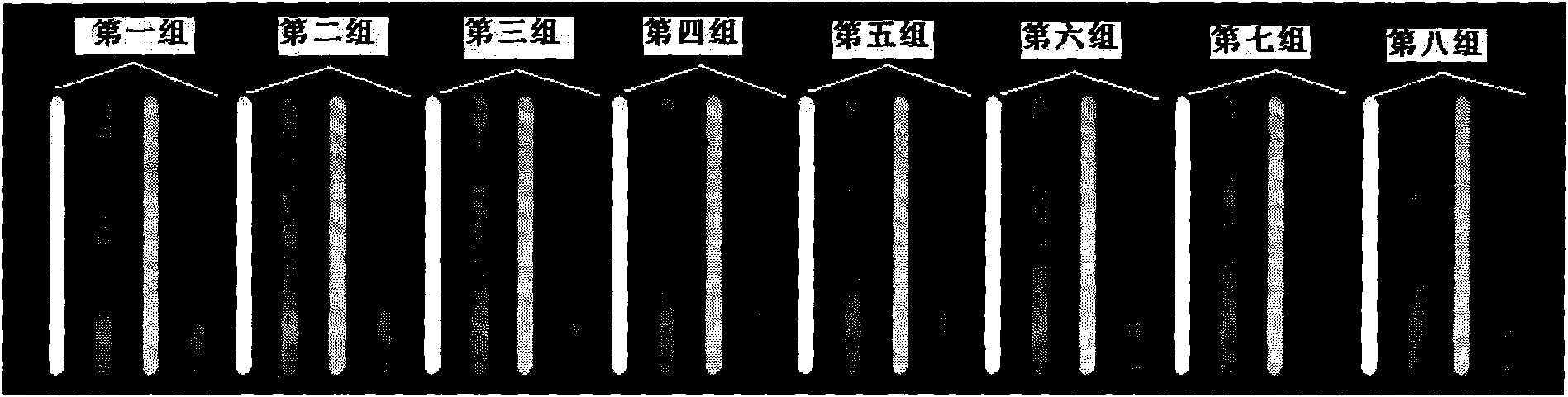
[0023] The measurement process of the present invention is as follows: 1) refer to figure 2 , taking 8 groups of color combination stripes as an example, each of four color stripes is a group (white, red, green, and blue), and the distance between the color stripes is M, and the prefabricated color projection stripes are as follows: figure 2 ;

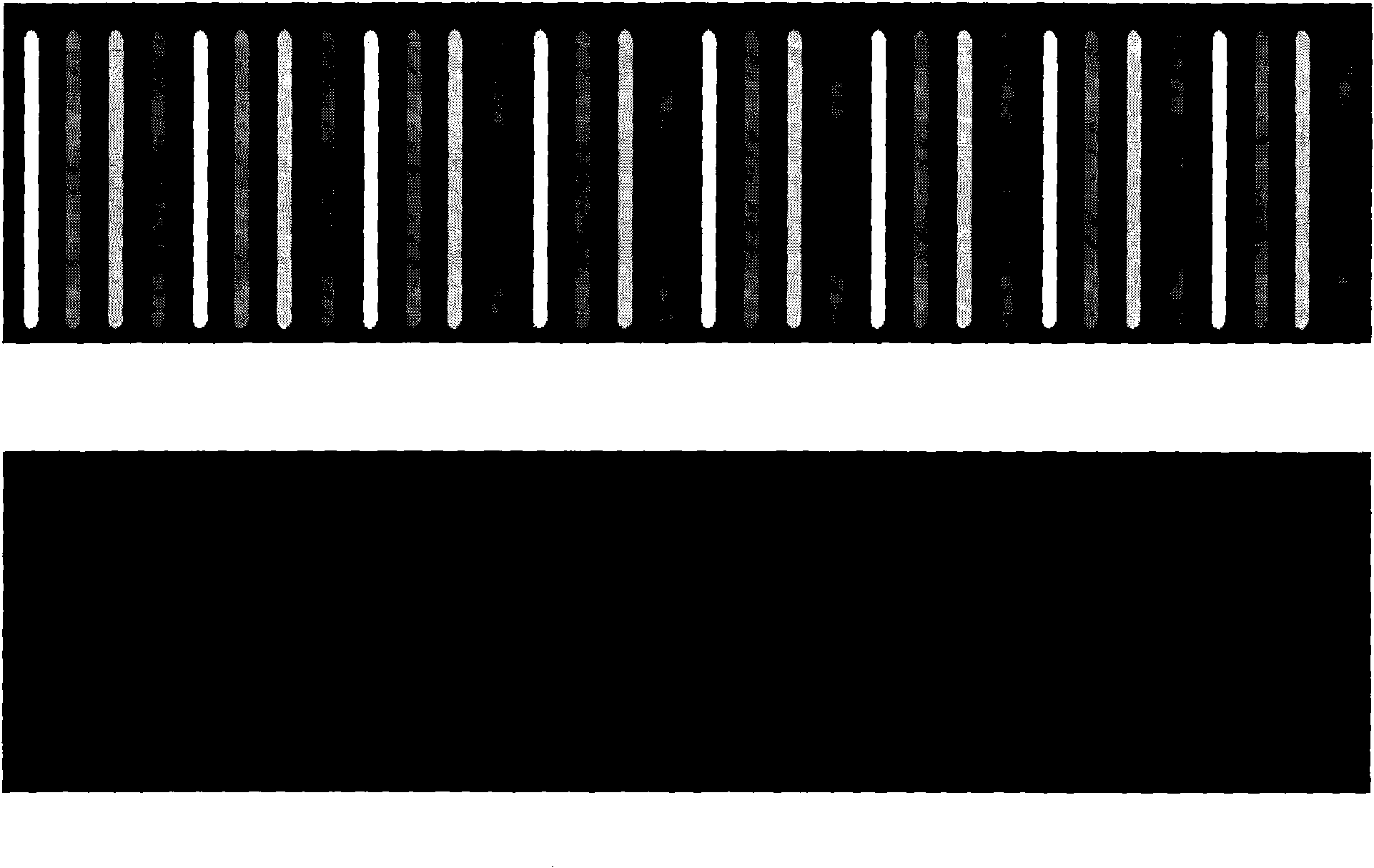
[0024] 2) see image 3 , replace the black and white stripes in the traditional projection with a single color combination stripe, code and project the color stripe group, that is, project ...


PUM


Abstract

The invention relates to a method for measuring an optical three-dimensional contour of space coding, which belongs to the field of photoelectric measurement. The method comprises the following steps: a strip in the prior binary coding is replaced by an idea for subdividing a binary coding strip by a color information strip; color information is easy to recognize, the contradiction between strip distance and strip recognition is solved, and a space point in a color strip distance in the previous step is measured in such a way of strip displacement multi-measurement, thereby being equivalent to further subdivide the measurement distance and preventing the problem of difficult strip recognition caused by denser projection light in such a way of displacement measurement; and finally the three-dimensional contour information of an object is obtained by integrating several measurement results. The invention can effectively solve the contradictions between strip coding and speed as well as strip distance and recognition in the three-dimensional contour measurement of structural light and ensure that the measuring speed reduction is prevented when the measuring precision is improved in the coding measurement of the structural light or the measuring speed can be improved under the condition of ensuring a certain precision.

Description

technical field [0001] The invention belongs to the field of photoelectric measurement, in particular to a space-encoded optical three-dimensional profile measurement method. Background technique [0002] Optical three-dimensional profilometry technology has always been a research hotspot in the field of three-dimensional sensing and metrology, and is widely used in manufacturing, computer-aided medicine, virtual reality, and cultural heritage protection. Because of its non-contact, non-destructive, fast speed, high precision and other characteristics, it becomes the most ideal means of contour shape measurement. [0003] The structured light coded three-dimensional profile measurement method demodulates the three-dimensional information of the measured object field according to the light field projected on the object and the geometric relationship between the projection system, the acquisition system and the measured object reference. Each projected light knife needs to be...

Claims


Application Information

Patent Timeline
IPC IPC(8): G01B11/25
Inventor 王昭黄军辉阳明高建民
Owner XI AN JIAOTONG UNIV
Learn More