Method of machining u-shaped groove of substrate of fragile material, removal method, boring method and chamfering method using the same method

A technology of brittle material substrates and processing methods, applied in stone processing equipment, metal processing equipment, fine working devices, etc., can solve problems such as poor symmetry, difficulty in forming chamfered processing surfaces 14, and difficulty in completely eliminating residual areas, etc., to achieve The effect of saving processing energy, suppressing the occurrence of defects such as micro cracks, and increasing the processing speed

Inactive Publication Date: 2009-12-23
MITSUBOSHI DIAMOND IND CO LTD
View PDF2 Cites 41 Cited by
  • Summary
  • Abstract
  • Description
  • Claims
  • Application Information

AI Technical Summary

Problems solved by technology

As a result, near the edge line 11 irradiated by the laser beam, the cracks generated by the thermal stress continue to grow, thereby forming an arc-shaped chamfered surface 14, but the laser beam is first irradiated to the edge line 10 of the glass substrate 10. end of P B Irregular residual areas formed nearby17
Even if the irradiation angle and irradiation conditions of the laser beam to the substrate 10 are varied, it is difficult to completely eliminate the residual area.
In addition, since the symmetry of the temperature distribution near the edge line is poor, it is difficult to form a stable chamfered surface 14, and defects such as microcracks may occur.

Method used


Image

  • Method of machining u-shaped groove of substrate of fragile material, removal method, boring method and chamfering method using the same method
  • Method of machining u-shaped groove of substrate of fragile material, removal method, boring method and chamfering method using the same method
  • Method of machining u-shaped groove of substrate of fragile material, removal method, boring method and chamfering method using the same method

Examples


Embodiment Construction

[0079] Embodiments of the present invention will be described below using the drawings. In the following embodiments, processing of a glass substrate will be described, but the same applies to other brittle material substrates.

[0080] (U-groove processing)

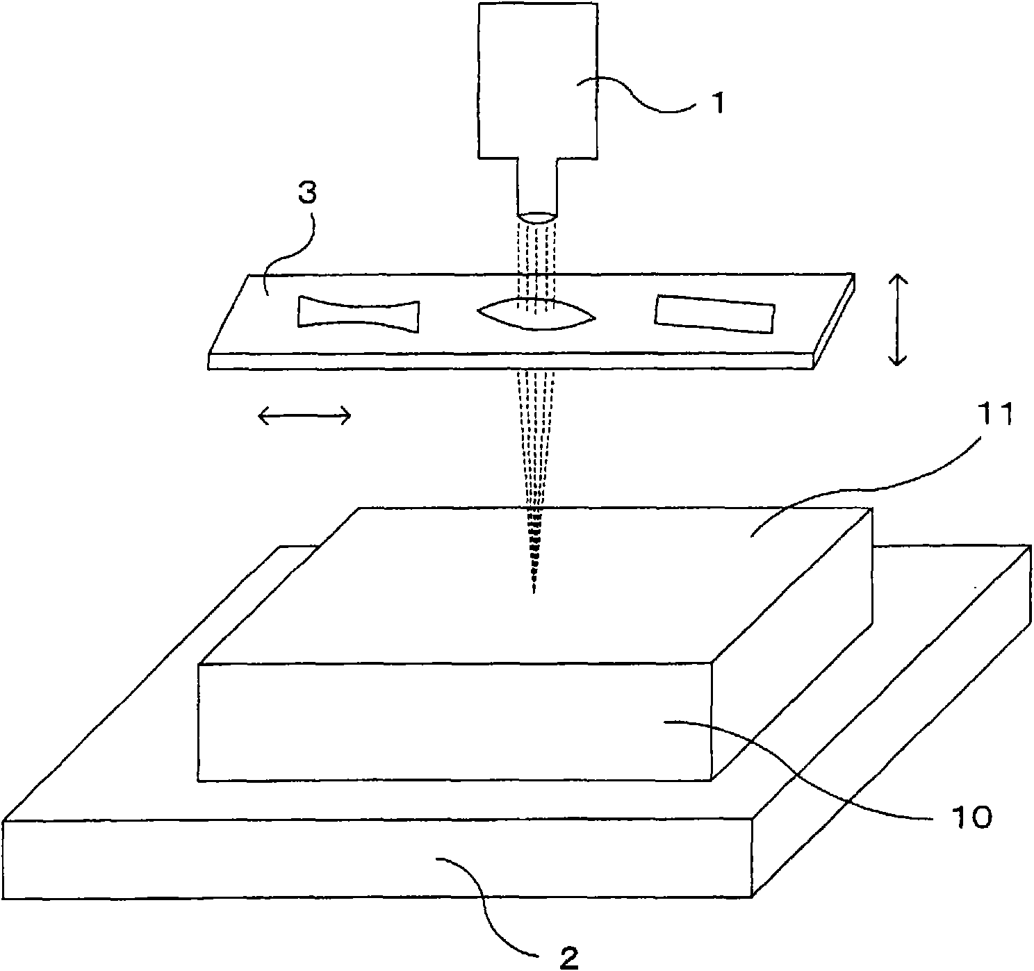
[0081] First, a method of forming a U-shaped groove on a glass substrate will be described. figure 1 It is a diagram showing the configuration state of the laser, the processing material, and the laser power distribution forming device when processing U-shaped grooves on the glass substrate. The laser light source 1 is arranged to face the substrate surface 11 of the glass substrate 10 . The stage 2 on which the glass substrate 10 is placed is movable relative to the laser light source 1 , and the scanning speed of the laser beam is controlled by the moving speed of the stage 2 . Furthermore, between the laser light source 1 and the substrate 10, an optical system 3 for adjusting the energy distribution and irradiati...


PUM


Abstract

A method of easily forming a linear or curved continuous or discontinuous U-shaped groove on a substrate surface, and a chamfering method using the same. Part of the surface of a substrate made of a fragile material is rapidly heated under laser irradiation conditions for forming the U-shaped groove consisting of a predefined combination of laser power, a laser irradiation area and scanning speed according to a substrate material to be machined, a groove width of the U-shaped groove to be formed, a depth and a shape of a groove surface, thereby exfoliating part of the substrate from the surface and forming the U-shaped groove. A chamfered face comprising a groove surface constituted of part of the U-shaped groove formed between an end surface segmented from an expected segmentation line and the substrate surface is formed by a method of scribing from an initial end of the expected segmentation line set on the bottom of the groove toward a terminal end by means of laser crack growth, a method of scribing by means of a cutter wheel or the like.

Description

technical field [0001] The present invention relates to a method for forming a U-shaped groove by rapidly heating a part of the surface of a substrate made of a brittle material, peeling off a part of the substrate from the surface, and performing removal processing or drilling processing on an object to be processed using the method Methods. Background technique [0002] For example, on a processing table of a precision machine, a brittle material substrate such as a glass substrate is used due to the property of a small linear expansion coefficient. Usually, this kind of processing table is composed of an upper mold and a lower mold, and an oil storage groove or a cooling channel for improving lubricity is formed on the contact surface of the upper mold and the lower mold. In order to form the oil storage groove or the cooling passage, it is necessary to form grooves on the glass substrate. In addition, mechanical methods and chemical methods are generally known as metho...

Claims


Application Information

Patent Timeline
Patent Type & Authority Applications(China)
IPC IPC(8): B23K26/00B23K26/38B28D5/00
CPCB23K26/0656B28D5/0011B23K26/4075B23K26/40B23K26/066B23K2103/50C03B33/033C03B33/04C03B33/091Y02P40/57B23K26/06B23K26/38
Inventor 森田英毅清水政二福原健司
Owner MITSUBOSHI DIAMOND IND CO LTD
Why Eureka
Try Eureka