Rotary compressor

A compressor and rotary technology, used in rotary piston machinery, rotary piston pumps, mechanical equipment, etc., can solve the problems of vibration in the wiring direction, broken pipes and other problems

Active Publication Date: 2009-12-23
DAIKIN IND LTD
View PDF1 Cites 3 Cited by
  • Summary
  • Abstract
  • Description
  • Claims
  • Application Information

AI Technical Summary

Problems solved by technology

[0005] However, the compressor of Patent Document 1 has the following problems. Because the load torque of the drive shaft fluctuates in one revolution, the rotational speed of the drive shaft and the motor rotor driving the drive shaft fluctuate with the fluctuation of the load torque. There was a problem of vibration in the wiring direction of the housing that fixed the stator of the motor
And, in the worst case, the pipes connected to the housing will be broken and damaged

Method used


Image

  • Rotary compressor
  • Rotary compressor
  • Rotary compressor

Examples


no. 1 approach

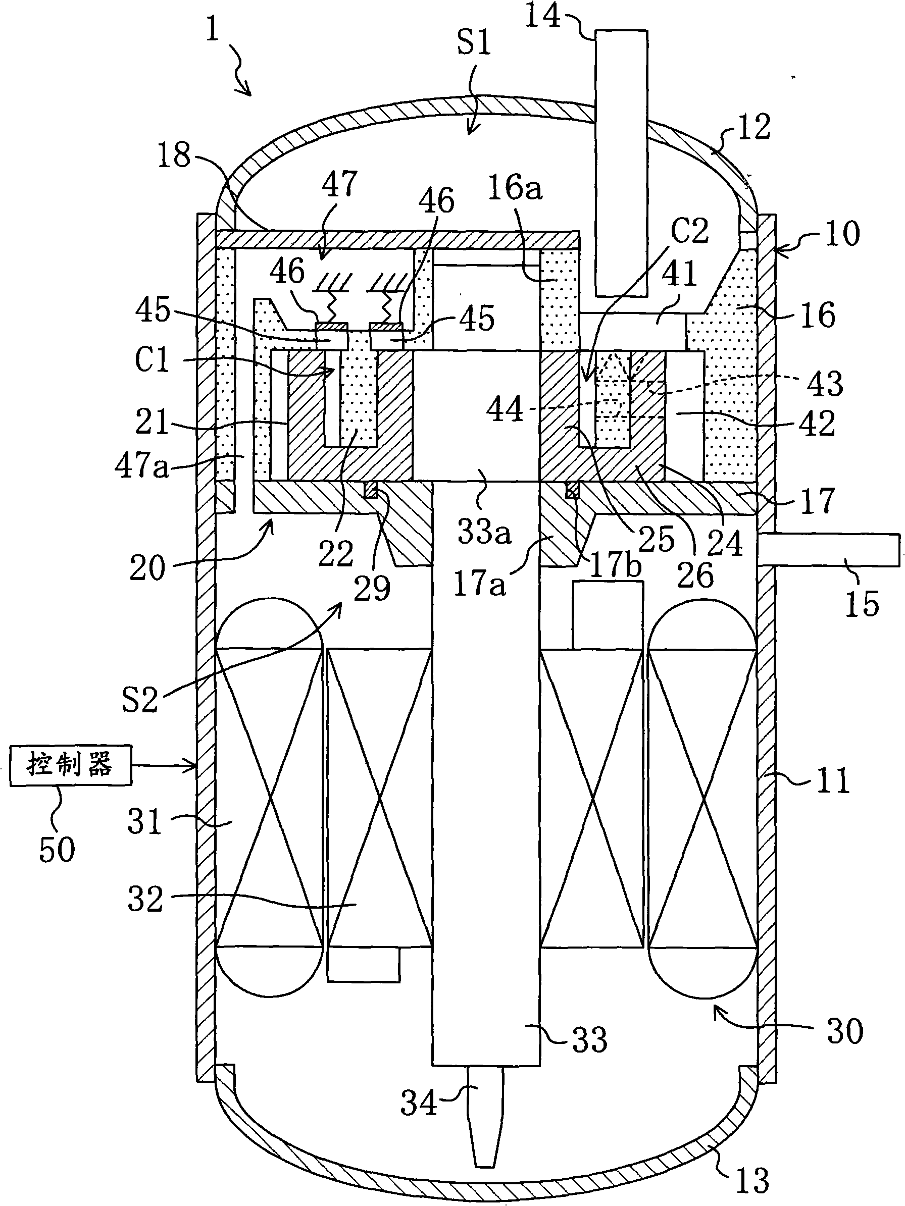
This first embodiment is as follows figure 1 The rotary compressor shown. The compressor 1 accommodates a compression mechanism 20 and a motor 30 for driving the compression mechanism 20 in a housing 10, and is configured as a fully enclosed type. The compressor 1 is used, for example, in a refrigerant circuit of an air conditioner (ari condit-ioning), to compress refrigerant sucked from an evaporator and sprayed to a condenser.

[0044] The casing 10 is composed of a cylindrical body 11 and an upper end plate 12 and a lower end plate 13 respectively fixed to the upper end and the lower end of the body 11 . The suction pipe 14 penetrates the upper end plate 12 , and the discharge pipe 15 penetrates the trunk portion 11 .

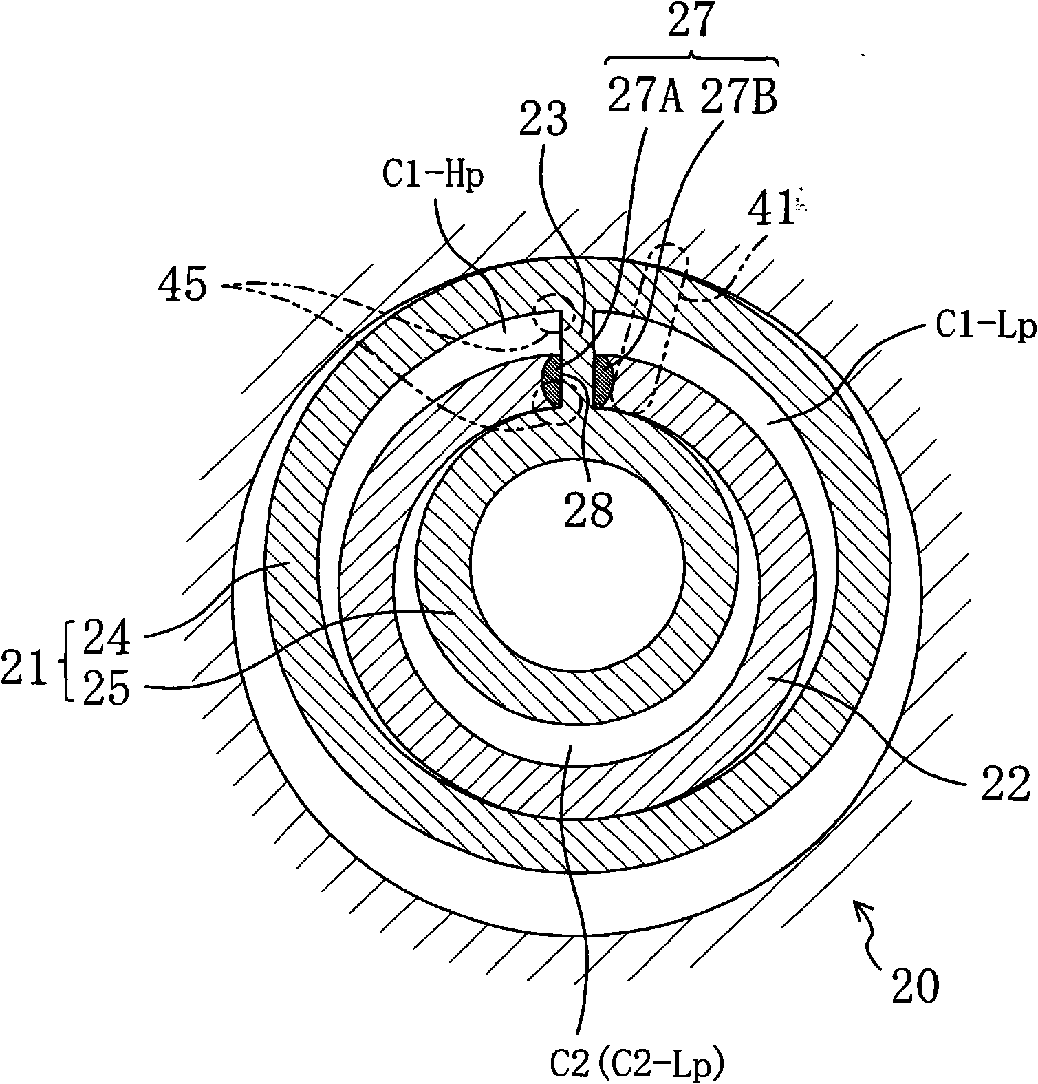
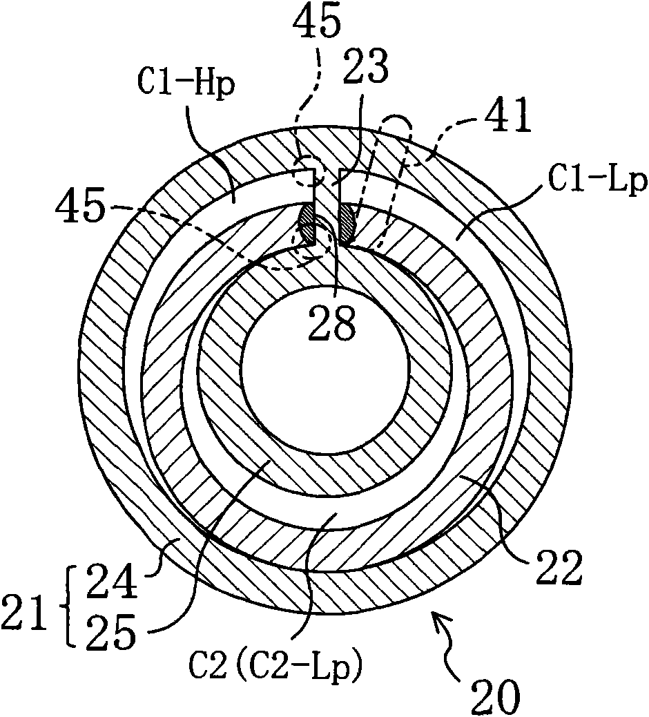
[0045] The compression mechanism 20 includes an upper cover 16 , a lower cover 17 and a cylinder 21 fixed on the casing 10 . The cylinder 21 has annular cylinder chambers C1 and C2 and is disposed between the upper cover 16 and the lower cover 17 . The u...

no. 2 approach

This second embodiment, such as Figure 7 and Figure 8 As shown, the configuration of the compression mechanism 20 in the first embodiment is changed. That is, in the present embodiment, the ring-shaped piston 52 is configured on the movable side and the cylinder 21 is on the fixed side, and the ring-shaped piston 52 rotates eccentrically with respect to the cylinder 21 .

[0088] The compression mechanism 20 includes an upper cover 16 and a piston body 55 . The upper cover 16 is integrally formed with the cylinder 21 . The piston body 55 is configured to rotate eccentrically relative to the cylinder 21 . In addition, in this embodiment, the lower cover 17 is omitted.

[0089] The cylinder 21 includes an annular outer cylinder portion 24 and an inner cylinder portion 25 formed coaxially with each other. The outer cylinder portion 24 and the inner cylinder portion 25 are provided on the lower surface of the end plate 26 of the upper cover 16 . Also, annular cylinder chamb...

no. 3 approach

This third embodiment, such as Figure 10 and Figure 11 As shown, the compression mechanism 20 of the first embodiment is configured to perform two-stage compression of refrigerant. That is, in the compression mechanism 20 of this embodiment, the outer cylinder chamber C1 constitutes the low-stage compression chamber, and the inner cylinder chamber C2 constitutes the high-pressure side compression chamber.

[0099] The compressor 1 is used, for example, to use carbon dioxide (CO 2) is a refrigerant, a refrigerant circuit that performs a cycle of two-stage compression and one-stage expansion. Although not shown in the figure, this refrigerant circuit is connected by refrigerant piping in order of a compressor 1 , a gas cooler, a receiver, an intercooler, an expansion valve, and an evaporator. In this refrigerant circuit, the high-pressure refrigerant discharged from the inner cylinder chamber C2 of the compressor 1 flows in the order of the radiator, liquid receiver, expansi...


PUM


Abstract

An annular cylinder chamber (C1, C2) of a cylinder (21) is partitioned into an outer cylinder chamber (C1) and an inner cylinder chamber (C2) with an annular piston (22). The cylinder (21) is caused to eccentrically rotate by driving an electric motor (30), thereby changing the volumes of the outer cylinder chamber (C1) and the inner cylinder chamber (C2). The volume ratio Vr of the inner cylinder chamber (C2) to the outer cylinder chamber (C1) is set at about 0.7. In this state, the output torque of the electric motor (30) is changed in accordance with a variation in the load torque in one turn of rotation.

Description

technical field [0001] The present invention relates to a rotary compressor, and more particularly to countermeasures against vibrations accompanying load torque fluctuations. Background technique [0002] Conventionally, as a rotary compressor having two cylinder chambers, for example, Patent Document 1 discloses a compressor that compresses refrigerant by changing the volume of the cylinder chambers due to the eccentric rotary motion of the annular piston. [0003] The compressor of Patent Document 1 includes a cylinder having an annular cylinder chamber and an annular piston arranged in the cylinder chamber. The cylinder is composed of an outer cylinder and an inner cylinder arranged concentrically with each other. That is, a cylinder chamber is formed between the outer cylinder and the inner cylinder, and the cylinder chamber is divided into an outer cylinder chamber and an inner cylinder chamber by the annular piston. The ring-shaped piston is configured to be driven ...

Claims


Application Information

Patent Timeline
IPC IPC(8): F04C28/08F04C18/32F04C23/00
CPCF04C2270/035F04C28/16F04C23/008F04C18/0215F04C18/045F04C23/001F04C18/3562F04C2270/125
Inventor 芝本祥孝清水孝志增田正典外岛隆造古庄和宏山际昭雄安田善纪
Owner DAIKIN IND LTD
Why Eureka
Try Eureka