Vacuum cleaner

A vacuum cleaner and dust collection technology, applied in the direction of vacuum cleaners, suction filters, cleaning equipment, etc., can solve the problems of affecting the work of the display, poor production process of the compression spring, distortion, etc., to achieve the valve plate stiffness is easy to ensure, reduce the action The effect of bad and simple processing technology

Inactive Publication Date: 2009-12-30
LG ELECTRONICS (TIANJIN) APPLIANCES CO LTD
View PDF0 Cites 8 Cited by
  • Summary
  • Abstract
  • Description
  • Claims
  • Application Information

AI Technical Summary

Problems solved by technology

[0015] However, the display 10 of the prior art adopts a compression spring. Because the production process of the compression spring is not good, it is difficult to control, and distortion will occur. In addition, the designed gap is maintained between the indicator and the housing, and the spring or the indicator and the housing are easily connected. Friction will affect the work of the display and cause bad

Method used


Image

  • Vacuum cleaner
  • Vacuum cleaner
  • Vacuum cleaner

Examples


Embodiment Construction

[0032] Below in conjunction with accompanying drawing and specific embodiment the present invention is described in further detail:

[0033] The working principle of the vacuum cleaner of the present invention is the same as that of the prior art, and the prior art can be referred to, so it will not be described again, and the same symbols as those of the prior art will be used. The difference between the present invention and the prior art is that the structure of the display is different , as detailed below:

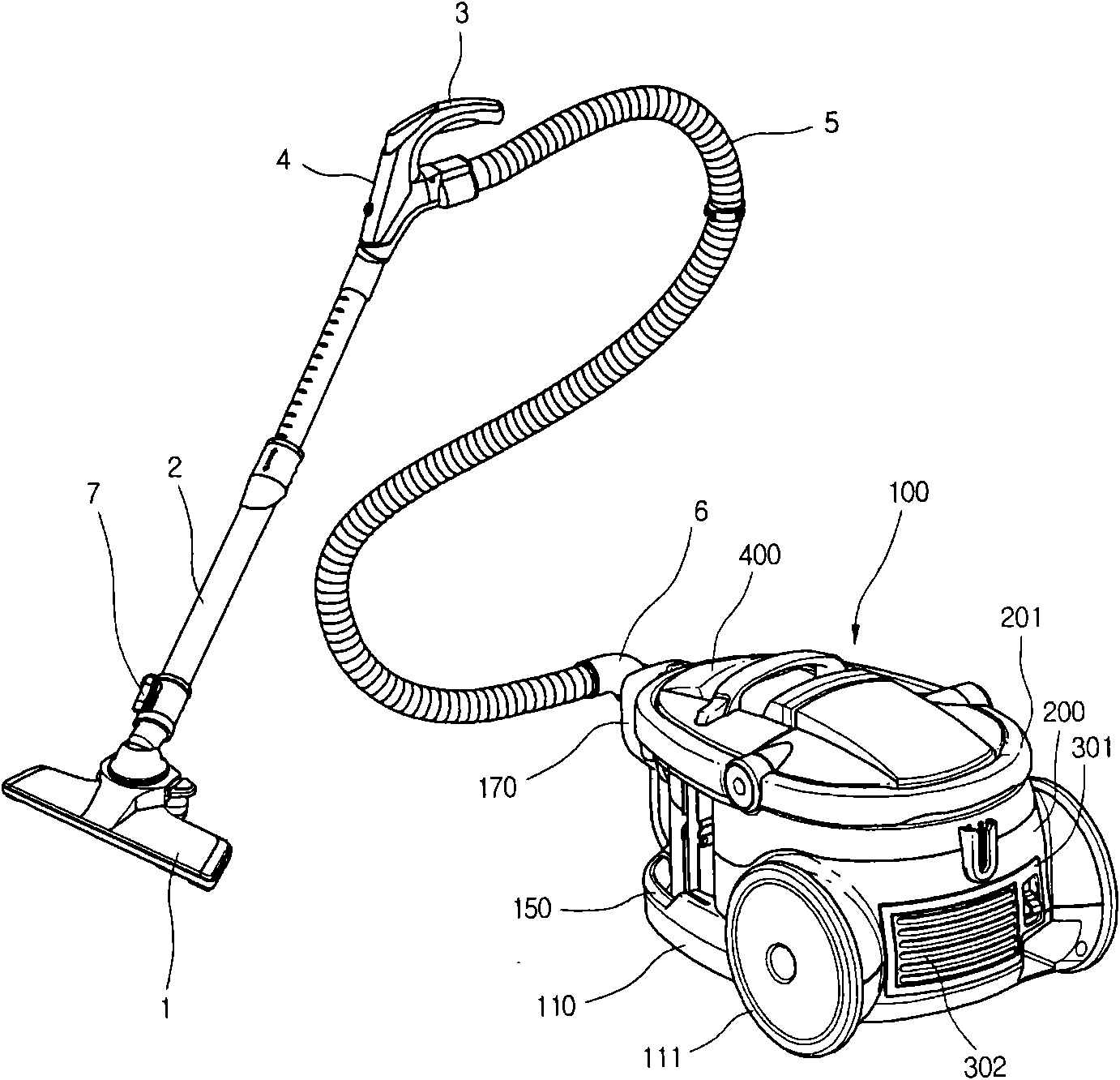
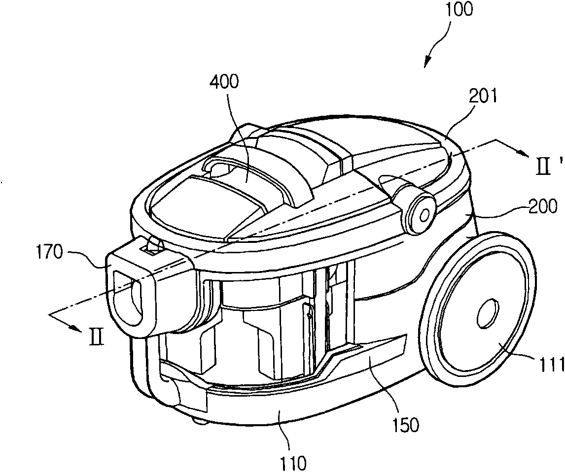
[0034] Such as figure 1 As shown, the vacuum cleaner of the present invention includes: a body 100 ; and a suction pipeline connected to the suction side of the body 100 . A fan and a dust collection unit 400 are provided inside the body 100 to send clean air to the outside after filtering out foreign objects in the air.

[0035] The suction line is a line for sucking in air and foreign matter using the suction force of the body 100 . Specifically, the suction pipel...


PUM


Abstract

The invention discloses a vacuum cleaner. A display which displays working state of a dust collecting cavity is arranged between the lower side of a top shell of the vacuum cleaner and the dust collecting cavity of a dust collecting unit, and consists of a shell, an indicating body which is positioned inside the shell, and a valve plate of which one end is fixed outside the lower part of the shell; the shell corresponding to the valve plate is provided with a through hole; communication of the inside of the display and the dust collecting cavity can be controlled through opening and closing of the valve plate; a lateral surface of the shell far from the first through hole is provided with a second through hole; the second through hole is communicated with atmosphere outside the cleaner through an intercommunicating pore; the top part of the shell of the display is provided with a transparent display window; and the top shell corresponding to the display window is provided with a display window opening. The vacuum cleaner adopts a valve plate type blade spring structure, has simple process, reduces friction between the indicating body and the shell, and has non friction between the valve plate and the shell.

Description

technical field [0001] The invention relates to a vacuum cleaner, in particular to a vacuum cleaner with a simple display structure and low noise. Background technique [0002] Generally, a vacuum cleaner is a household appliance that uses suction generated by a fan and a motor to forcibly inhale external air, and uses a filter component to collect foreign objects sucked together with the air to clean the indoor environment. [0003] In the dust collection unit of the vacuum cleaner, the filter mechanism for filtering out foreign matter includes a porous filter unit for forcibly filtering foreign matter in the passing air and a cyclone dust collection unit for collecting foreign matter by using the centrifugal force in the air cyclone flow. [0004] Such as figure 1 As shown, the prior art vacuum cleaner includes: a body 100 ; and a suction pipeline connected to the suction side of the body 100 . A fan and a dust collection unit 400 are provided inside the body 100 to send...

Claims


Application Information

Patent Timeline
Patent Type & Authority Applications(China)
IPC IPC(8): A47L5/28A47L9/19
Inventor 吕新
Owner LG ELECTRONICS (TIANJIN) APPLIANCES CO LTD
Why Eureka
Try Eureka