

Polishing grinding head
A polishing grinding and grinding seat technology, applied in the field of grinding and polishing equipment, can solve the problems of difficulty in realizing multi-degree-of-freedom arbitrary swing, high crushing rate, high noise, etc. Effect
- Summary
- Abstract
- Description
- Claims
- Application Information
AI Technical Summary
Problems solved by technology
Method used
Image

Examples
Embodiment Construction
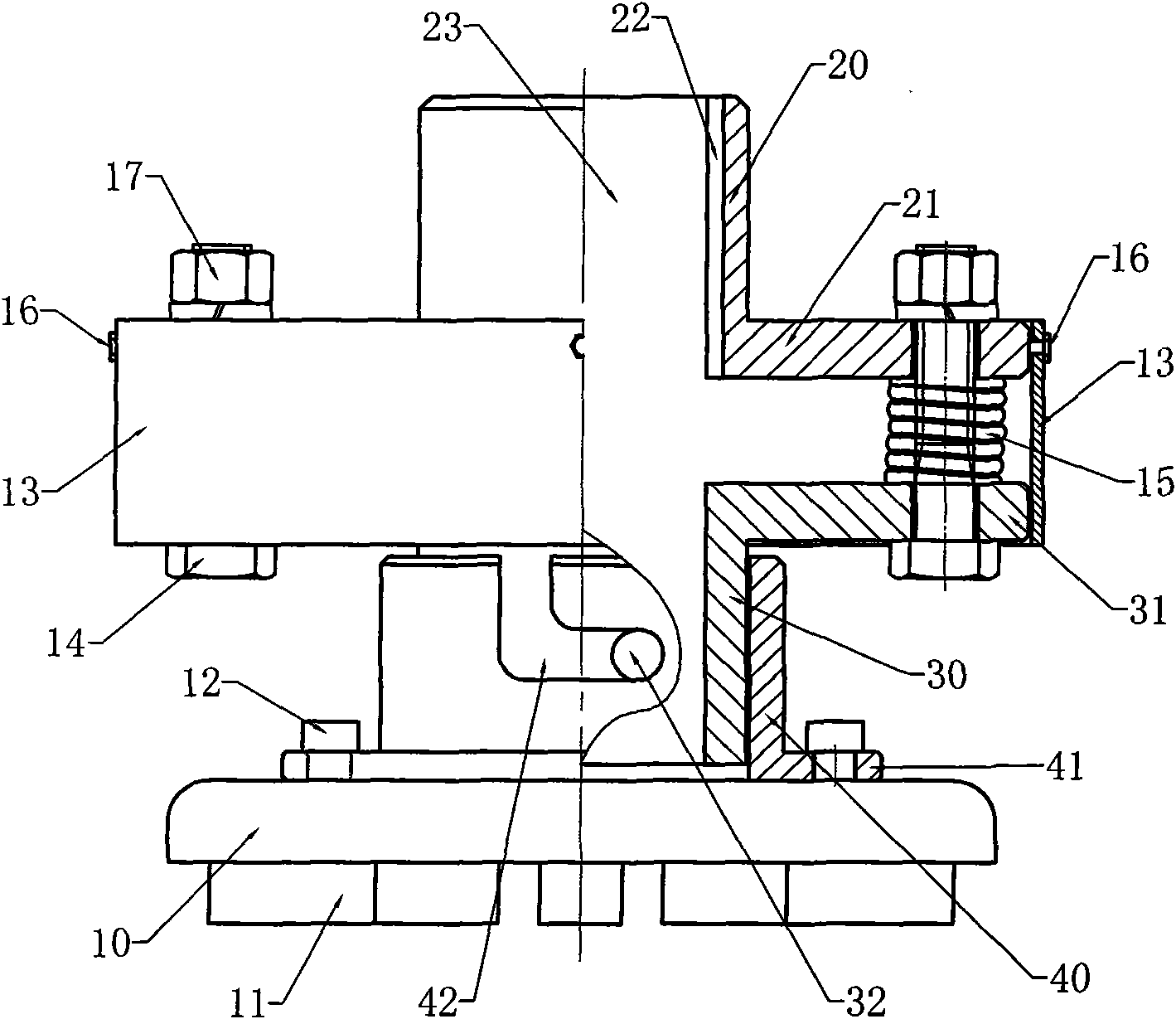
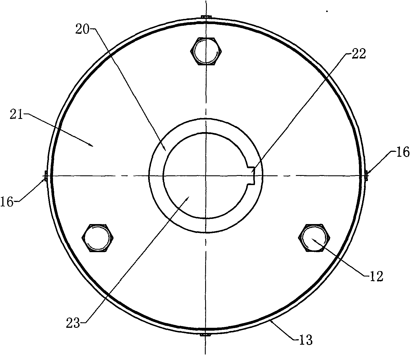
[0020] refer to Figure 1-Figure 2 , a polishing grinding head, comprising a grinding disc 10 and a grinding head installation structure, above the grinding disc 10, a cylindrical lower grinding base 40, a cylindrical middle grinding base 30 and a cylindrical upper grinding base 20 are arranged successively, and the lower grinding base The lower end of the base 40, the upper end of the middle grinding base 30 and the lower end of the upper grinding base 20 are respectively provided with flanges, the grinding disc 10 is connected with the lower grinding base flange 41 by bolts 12, and the cylindrical lower grinding base 40 is overlaid on the on the cylindrical middle grinding base 30 and is connected by a buckle device, and the buckling device is composed of a bayonet pin 32 radially arranged on the cylindrical middle grinding base 30 and a lower grinding base 40 which is matched with the bayonet The "L" shaped card slot 42 constitutes. Between the cylindrical middle grinding ...
PUM
 Abstract
Description
Claims
Application Information