Device and method for controlling DC motor to lower roller shutter door at constant speed

A technology of DC motors and control devices, applied in the direction of DC motor speed/torque control, door/window protection devices, control systems, etc. Working at high pressure and high temperature for a long time, reducing production costs and prolonging the service life

Inactive Publication Date: 2009-12-30
FUJIAN ANLIN INTELLIGENT SCI & TECH
View PDF0 Cites 6 Cited by
  • Summary
  • Abstract
  • Description
  • Claims
  • Application Information

AI Technical Summary

Problems solved by technology

[0004] When the rolling door moves upward, since the voltage at both ends of the DC motor 1 does not change much, the speed of dragging the rotating shaft is relatively stable, so that the rolling door can basically maintain a constant speed and a stable state when the rolling door moves upward; Slowly put down, as the door panel of the rolling shutter door goes down more and more, its center of gravity gradually moves down from the center of the rotating shaft, and the gravity it receives gradually increases, so it drives the rotating shaft to rotate faster and faster. At the same time, its gravitational potential energy is also transformed into The electric energy is supplied to the DC motor 1, at this time, the DC motor 1 is equivalent to a generator, and the voltage at both ends increases rapidly (it can be increased from 24V under normal conditions to more than 63V, which is related to factors such as the size of the door body mechanism), and the driving shaft rotates rapidly When the rolling door is lowered, the downward speed of the rolling door will become faster and faster due to the increase in acceleration until it is completely lowered; especially in some large shopping malls or garages, the weight of the rolling door is often very large, and the downward speed is even more amazing. At the moment of stopping, the lower end of the rolling door hits the ground heavily, which not only easily damages the structure of the rolling door body, the motor and the floor, but also shortens the service life of the DC motor 1 due to prolonged heating, and the downward speed of the rolling door is uncontrollable, which easily poses a threat to the human body ,There are security risks
[0005] In order to overcome the above-mentioned defects, someone now connects a load 30 in parallel at both ends of the DC motor 1, such as figure 2 As shown, the load 30 can shunt the current in the circuit, thereby reducing the voltage at both ends of the DC motor 1, reducing the output power of the DC motor 1, and driving the rotation speed of the rotating shaft to decrease, thereby reducing the downward speed of the rolling door; , connect the load 30 to the circuit, but since the DC motor 1 will only turn into a generator after the shutter door is lowered for a certain distance, it will reduce its working efficiency during normal operation; The current of the load 30 is very large, so it will consume a large amount of electric energy, and it is also working when the rolling door is in normal operation, resulting in a large amount of waste of electric energy, and the required load 30 must have enough power to be actually used, otherwise, The load 30 will be damaged due to overload, which further consumes electric energy; the high-power load 30 has high cost, which increases the manufacturing cost of the DC motor 1, and at the same time, the load 30 generates a large amount of heat, which makes the local temperature too high and affects the service life of other components.

Method used


Image

  • Device and method for controlling DC motor to lower roller shutter door at constant speed
  • Device and method for controlling DC motor to lower roller shutter door at constant speed
  • Device and method for controlling DC motor to lower roller shutter door at constant speed

Examples


Embodiment Construction

[0023] The present invention will be described in detail below in conjunction with specific embodiments.

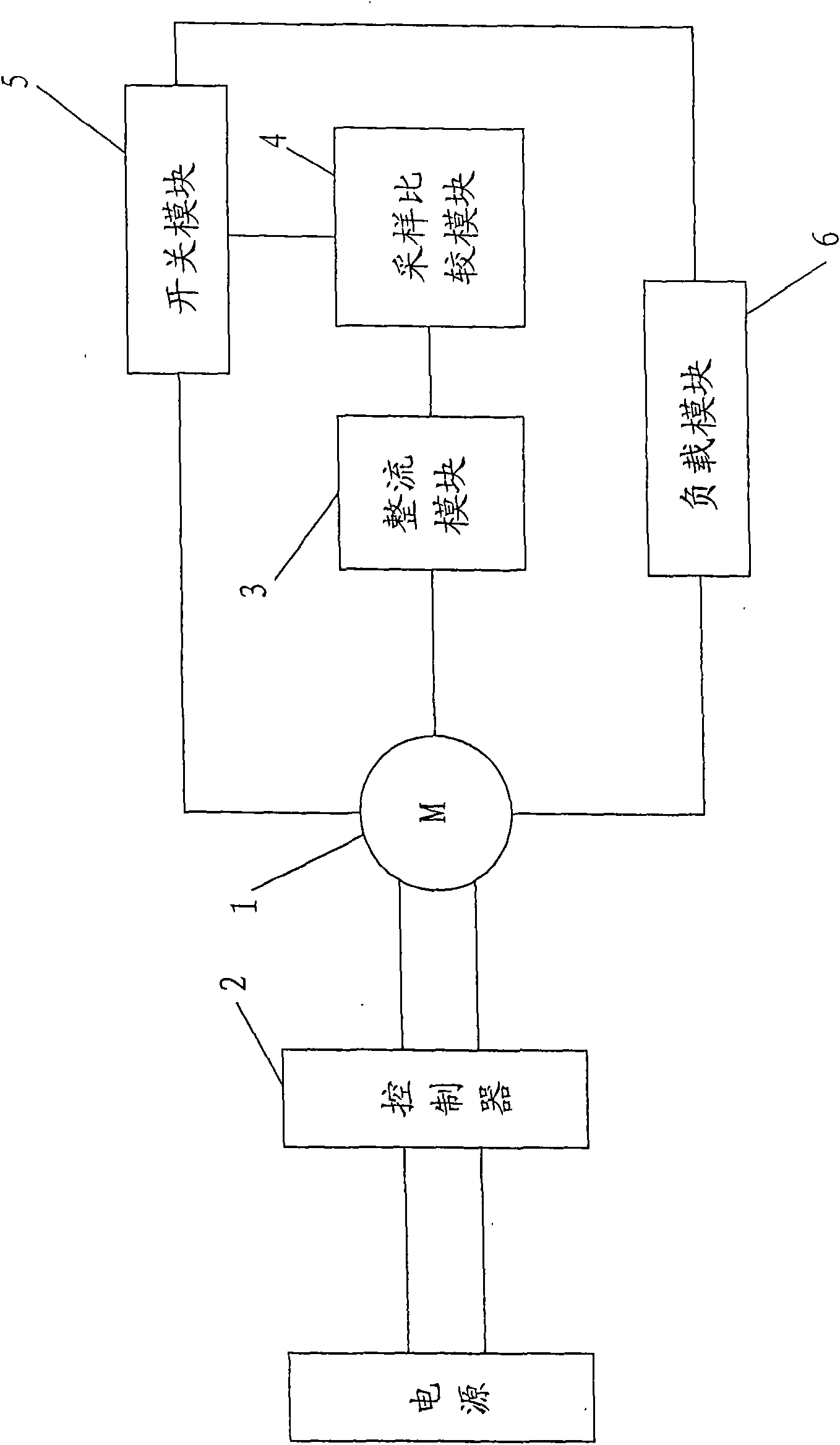
[0024] image 3 Shown is a preferred embodiment of the present invention, including a rectification module 3 , a sampling module 4 , a comparison module 7 , a switch module 5 and a load module 6 .

[0025] The rectifier module 3 is connected in parallel to the two ends of the DC motor 1, and rectifies the voltage signal at both ends of the DC motor 1. In this embodiment, a bridge rectifier circuit is selected, such as Figure 5 As shown, the bridge rectifier circuit is formed by two-to-two connection of four diodes. This is a known technology, so it will not be described again.

[0026] The output end of the rectification module 3 is connected to the sampling end of the sampling module 4 , and the sampling module 4 samples the rectified voltage value and transmits the voltage value to the connected comparison module 7 .

[0027] The output end of the sampling module 4 i...


PUM


Abstract

The invention discloses a control device of a DC motor for lowering a roller shutter door at constant speed, which comprises a rectifying module, a sampling comparison module, a switch module and a load module, wherein the switch module is serially connected with the load module and then parallelly connected to both ends of the DC motor; the input end of the rectifying module is parallel connected to both ends of the DC motor to rectify voltage signals at both end of the DC motor; and the sampling comparison module is connected with the output end of the rectifying module and he switch module and samples the rectified voltage signals, and the sampling comparison module sends out a control signal to the switch control according to a comparison result after a sampling value is compared with a setting value. The control device can block voltage at both ends of the DC motor within a certain range so as to lower the roller shutter door at constant speed, prolong the service life, and eliminate potential safety hazard. The invention also discloses a method for controlling the DC motor to lower the roller shutter door by using the device.

Description

[0001] technical field [0002] The invention relates to a DC motor for driving a rolling door to go up and down, in particular to a DC motor control device and method for making a rolling door go down at a constant speed. Background technique [0003] Due to its advantages of high safety performance and small footprint, the rolling shutter door is now used in more and more fields. The current rolling shutter door is generally driven by a DC motor, and its circuit connection is as follows: figure 1 As shown, the DC motor 1 (M) is connected to the power supply through the controller 2, and the controller 2 controls whether the DC motor 1 is started or not, and loads the power supply voltage in different directions, and then the DC motor 1 drives the upper end of the rolling door. The rotating shaft rotates in different directions to make the shutter door go up or down. [0004] When the rolling door moves upward, since the voltage at both ends of the DC motor 1 does not change...

Claims


Application Information

Patent Timeline
Patent Type & Authority Applications(China)
IPC IPC(8): E06B9/68H02P7/00
Inventor 刘王雍杰陈锦山施进生
Owner FUJIAN ANLIN INTELLIGENT SCI & TECH
Why Eureka
Try Eureka