Expansion tube type liner hanger

A liner hanger and expansion tube technology, which is applied in the field of oil drilling, can solve problems such as complex operation, liner falling off, and sealing failure, and achieve the effects of improving cementing quality, improving fluidity, and good sealing effect

Inactive Publication Date: 2009-12-30
PETROCHINA CO LTD
View PDF0 Cites 17 Cited by
  • Summary
  • Abstract
  • Description
  • Claims
  • Application Information

AI Technical Summary

Problems solved by technology

Whether it is a mechanical or hydraulic liner hanger, the upper part of the liner hanger is prone to failure after a certain period of service. Because the liner cement ring cannot achieve the sealing effect after a long period of time, it affects the development effect and follow-up operations.
In addition, conventional mechanical and hydraulic liner hangers are designed with more mechanical parts in the radial structure in order to meet the suspension and setting functions, resulting in a small inner diameter of the hanger, and the tool will received some restrictions
Other conventional liner hangers are difficult to set and hang in horizontal wells
Generally, the liner hanger is designed with a reverse buck

Method used


Image

  • Expansion tube type liner hanger
  • Expansion tube type liner hanger
  • Expansion tube type liner hanger

Examples


Embodiment 1

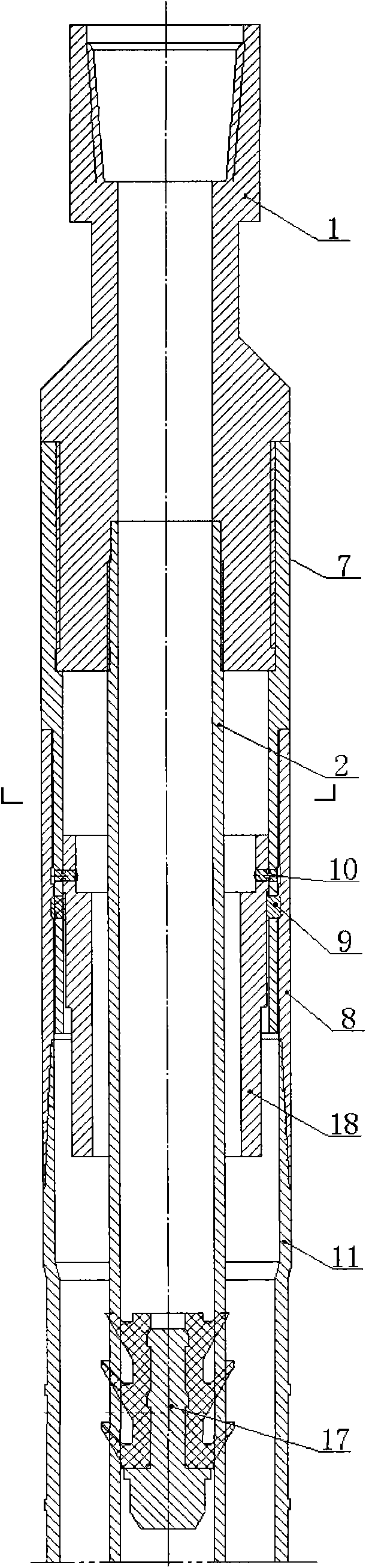
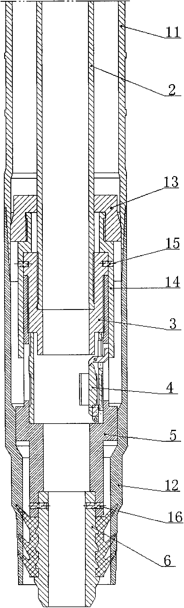
[0042] Example 1: Take one in 9 5 / 8 "Suspend 7" casing in the technical casing, and the used expansion tube type liner hanger is an example, and the invention is described in further detail. The outer diameter of the expansion cone 13 is 195 mm, that is, the inner diameter of the expansion tube 11 is 195 mm after the operation is completed.

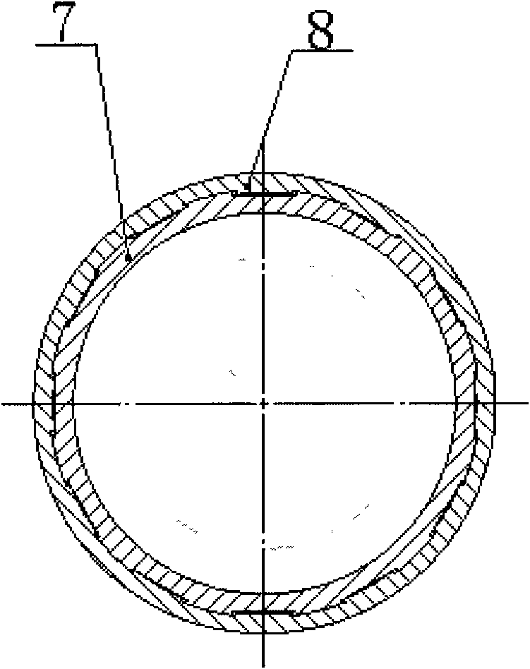
[0043] refer to figure 1 . The expansion tube type tail pipe hanger of the present invention is mainly composed of a feeding joint 1, a center pipe 2, a nut 3, a float valve assembly 4, a tail pipe rubber plug hanger 5, a tail pipe rubber plug 6, a muff 7, Spline sleeve 8, key 9, shear pin 10, expansion pipe 11, tie-back cylinder 12, expansion cone 13, float valve closing sleeve 14, pin 15, shear nail 16, drill pipe rubber plug 17 and top sleeve 18 . The feed-in joint 1 has a central hole, and the top of the feed-in joint 1 has an internal thread, which can be connected to the upper drill pipe during construction.

[0044] The low...

Embodiment 2

[0056] Embodiment 2: The difference from Embodiment 1 is that the cross-section of the annular boss on the outer wall of the expansion tube 11 is triangular.

Embodiment 3

[0057] Embodiment 3: The difference from Embodiment 1 is that the section of the annular boss on the outer wall of the expansion tube 11 is trapezoidal.


PUM

PropertyMeasurementUnit
Widthaaaaaaaaaa
Heightaaaaaaaaaa
Outer diameteraaaaaaaaaa

Abstract

An expansion tube type liner hanger is applied to liner hanging construction for petroleum drilling and completion. The liner hanger mainly comprises a feeding joint, a central tube, a nut, a float valve, a releasing drum, an expansion tube, a tieback drum, an expansion cone, closure sleeves of the float valve, a drill pipe plug and a releasing top sleeve; the lower part of the feeding joint is connected with the central tube by an internal thread; the lower end of the releasing drum is connected with the upper end of a splined sleeve by a spline; the lower end of the splined sleeve is connected with the expansion tube by a thread; the outer wall of the expansion tube is provided with a ring-shaped bulge; the lower end of the expansion tube is connected with the upper end of the tieback drum; expansion device modules are connected in the tieback drum and at the lower end of the central tube; a hanging seat of a liner plug and the outer wall of the nut are provided with the closure sleeves of the float valve; the closure sleeves of the float valve are connected with the expansion cone; the closure sleeves of the float valve are connected with the nut by pins; the outer wall of the expansion tube is provided with a metal bulge; hanging and setting are completed by interference fit between the metal bulge and an outer casing tube, therefore, the liner hanger is not influenced by the gravity and slip eccentricity like the conventional liner hangers.

Description

technical field [0001] The invention relates to the technical field of petroleum drilling, in particular to a special tool for hanging a well drilling and completion liner, which is a liner hanger Background technique [0002] Generally, the liner hanger used for drilling and completion is mechanical or hydraulic. After the drill pipe is connected to the liner hanger and the liner is in place, the slips on the hanger are opened and attached to the outer layer by mechanical action or hydraulic method. On the inner wall of the technical casing, the slips can hang the weight of the tail pipe. Generally, cementing is performed after the liner hanger is suspended. The current mechanical or hydraulic liner hangers can be divided into two types: sealed and non-sealed in terms of function: (1) The hanger that can realize the top seal can continue to operate after the cement injection is completed, and the deformation of the rubber parts is realized. Sealing of the hanging part; (2...

Claims


Application Information

Patent Timeline
IPC IPC(8): E21B23/01E21B33/13
Inventor 高向前霍海生张立新李益良孙冬梅李涛毕秀玲
Owner PETROCHINA CO LTD
Why Eureka
Try Eureka