Ball valve

A ball valve and valve seat technology, applied in the field of valve devices, can solve the problems of short service life, wear and leakage of valve seat and ball sealing surface

Active Publication Date: 2009-12-30
星箭科技股份有限公司
View PDF0 Cites 10 Cited by
  • Summary
  • Abstract
  • Description
  • Claims
  • Application Information

AI Technical Summary

Problems solved by technology

Since the fixed ball and ball valves all have floating valve seats, the valve seat moves after being subjected to medium pressure or spring action, so that the sealing ring is pressed tightly on the ball to ensure sealing, but the ball is fixed, and the valve seat is always tight. Pressure on the ball, so there is always the problem of wear and tear between the valve seat and the ball sealing surface, the service life is short, and the switching process is a dynamic sealing process, the dynamic force of the valve seat is likely to cause uneven sealing and leakage, and the sealing reliability is poor; The small-diameter environment uses a floating ball valve. The ball of the ball valve is floating. Under the action o

Method used


Image

  • Ball valve
  • Ball valve
  • Ball valve

Examples


Embodiment

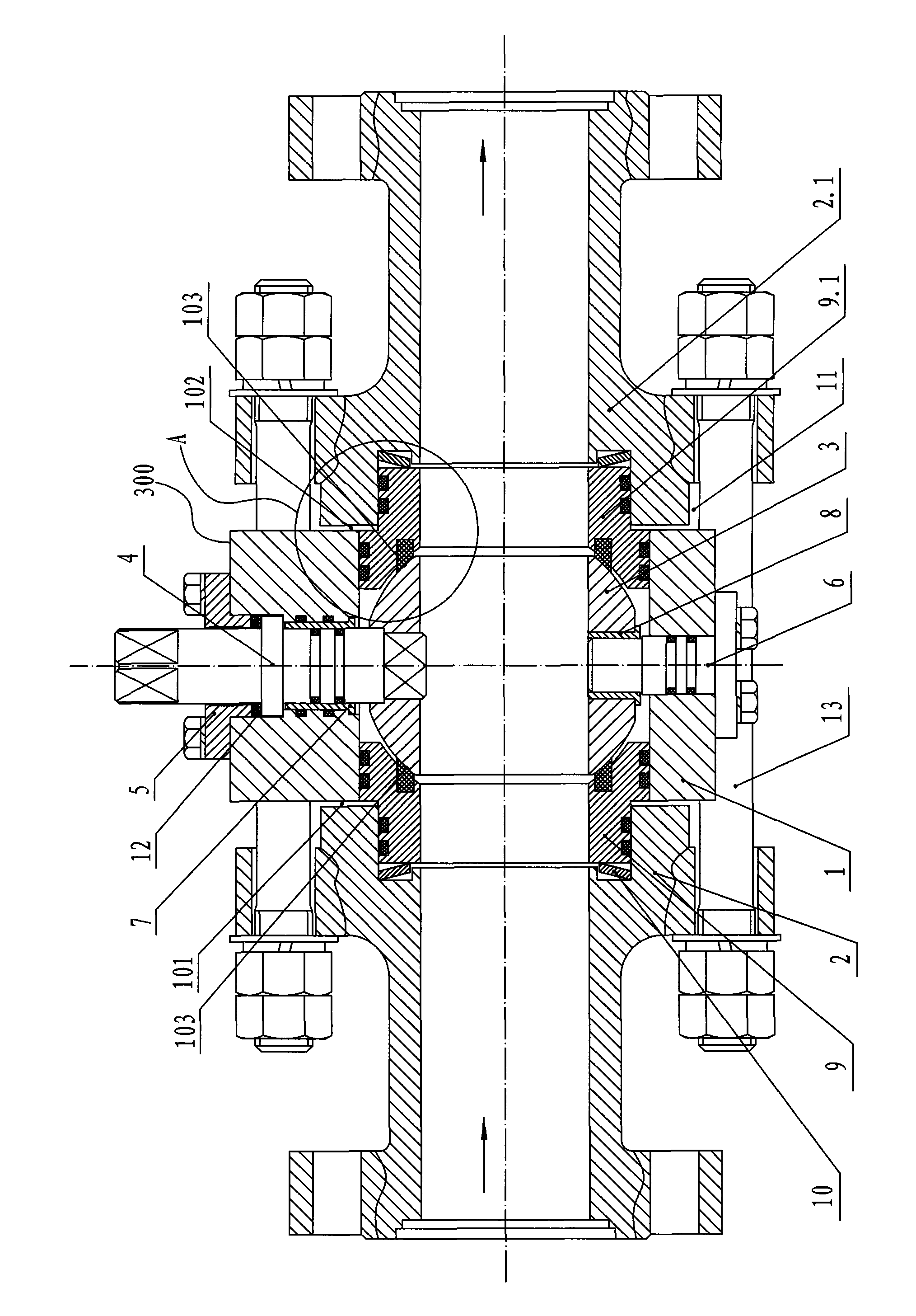
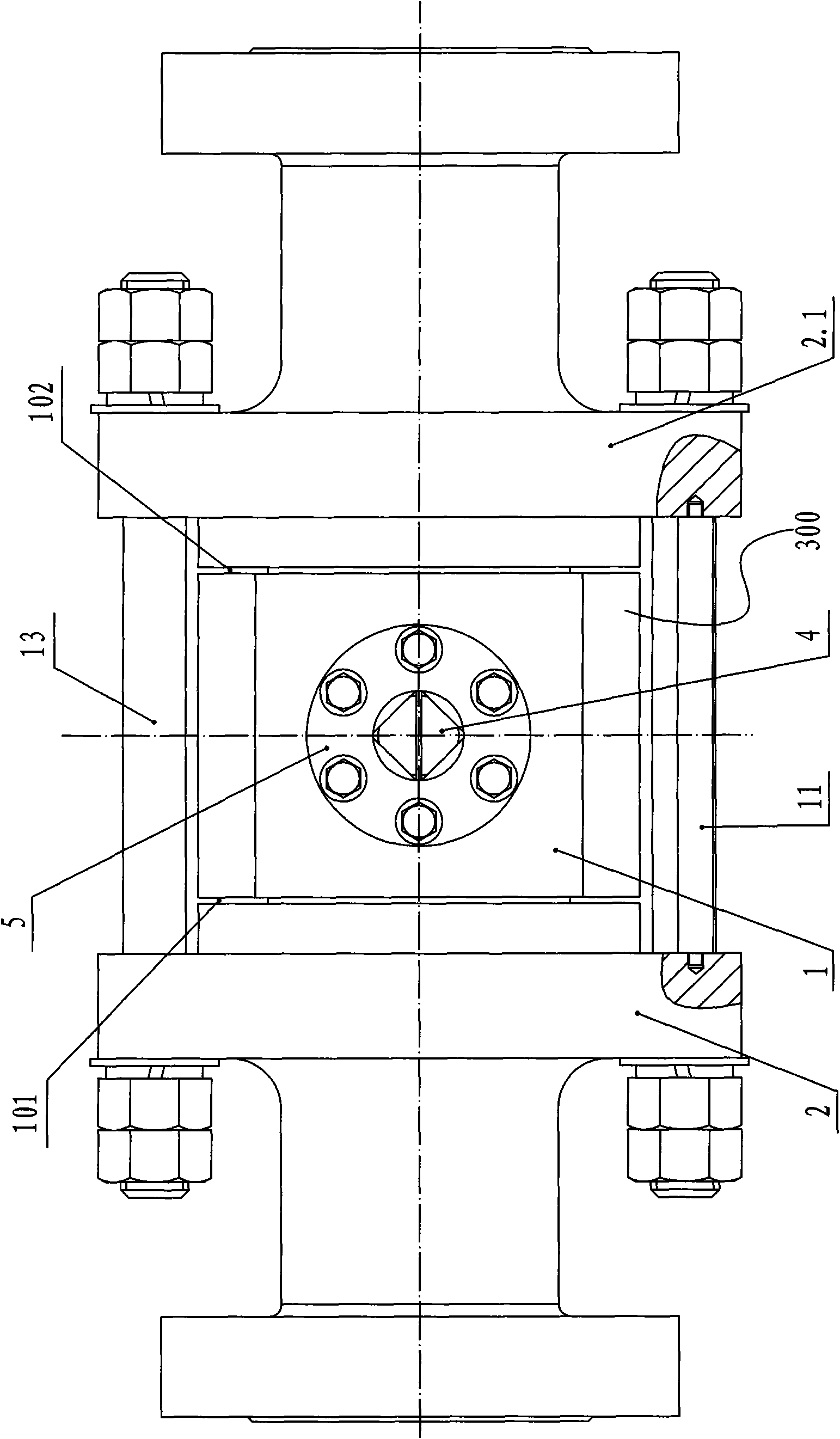
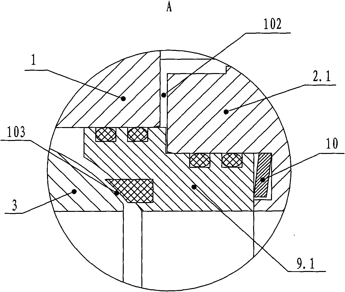
[0019] like figure 1 and figure 2 A ball valve is shown, which includes a main valve body assembly 300, a valve seat connected to the main valve body assembly 300, and an auxiliary valve body connected to one end of the valve seat, and a disc is arranged between the valve seat and the auxiliary valve body. type spring 10, the valve seat includes a left valve seat 9 and a right valve seat 9.1, and the auxiliary valve body includes a left auxiliary valve body 2 and a right auxiliary valve body 2.1, and the left end of the left valve seat 9 is slidingly fitted on the left auxiliary valve body. The right end of the inner chamber of the valve body 2 and the right end of the left valve seat 9 are slip-fitted on the left end of the inner chamber of the main valve body 1, and between the left valve seat 9 and the left auxiliary valve body 2 and between the left valve seat 9 and the main valve body 1 O-rings are provided between them to ensure the sealing performance between each oth...


PUM


Abstract

The invention relates to a ball valve. A main valve body assembly (300) comprises a main valve body (1), a ball body (3) which is positioned in the main valve body (1), an upper shaft (4) which is rotatably matched with the main valve body (1), a pressure cover (5) which is connected with the main valve body (1) and axially positions the upper shaft (4) and a lower shaft (6) which is connected with the main valve body (1), wherein the upper shaft (4) is fixedly connected with the upper end of the ball body (3), the lower end of the ball body (3) is rotatably connected with the lower shaft (6), the right end of a left valve seat is in slide connection with the left end of the main valve body (1), the left end of a right valve seat 9.1 is in slide connection with the right end of the main valve body (1), and the vertical distance between the right end face of a left auxiliary valve body (2) and the left end face of a right auxiliary valve body (2.1) is larger than the axial distance of the main valve body (1). Compared with the prior art, the invention has both of the advantages of a float ball valve and a fixed ball valve, and also has small operating torque, long service life and better sealing reliability.

Description

technical field [0001] The invention belongs to the field of valve devices, in particular to a ball valve. Background technique: [0002] At present, ball valves are mainly used in pipelines to cut off, distribute and change the flow direction of media. The ball valve has small fluid resistance, simple structure, the sealing surface of the ball and the valve seat is isolated from the medium, the channel is flat and smooth, and it is not easy to deposit the medium, and it is not only suitable for general working medium, but also suitable for medium with harsh working conditions, and has been widely used In petroleum, chemical industry, power generation, papermaking, atomic energy, aviation, rocket and other fields, as well as in people's daily life. [0003] The valve body of the ball valve can be integral or combined. In the prior art, fixed ball valves are used in high-pressure and large-diameter environments. The upper and lower shafts of the ball valve are fixed on the ...

Claims


Application Information

Patent Timeline
IPC IPC(8): F16K5/06F16K5/08F16K27/06
Inventor 郑科辉竺国荣
Owner 星箭科技股份有限公司
Why Eureka
Try Eureka