
Flow control device for steel ball flaw detection

A technology of flow control device and steel ball, which is applied in the flow control of electric devices, etc. It can solve the problems that steel balls are easily magnetized, impurities are easy to adhere to the surface, and affect cutting and cleaning efficiency, so as to achieve low power consumption and improve work efficiency. efficiency effect

Active Publication Date: 2009-12-30
JIANGSU LIXING GENERAL STEEL BALL
View PDF0 Cites 3 Cited by
  • Summary
  • Abstract
  • Description
  • Claims
  • Application Information

AI Technical Summary

Problems solved by technology

However, with this device, the steel ball is easily magnetized, and impurities are easily attached to the surface of the magnetized steel ball during subsequent processing, which affects the cutting and cleaning efficiency.

Method used


Image

  • Flow control device for steel ball flaw detection

Examples


Embodiment Construction

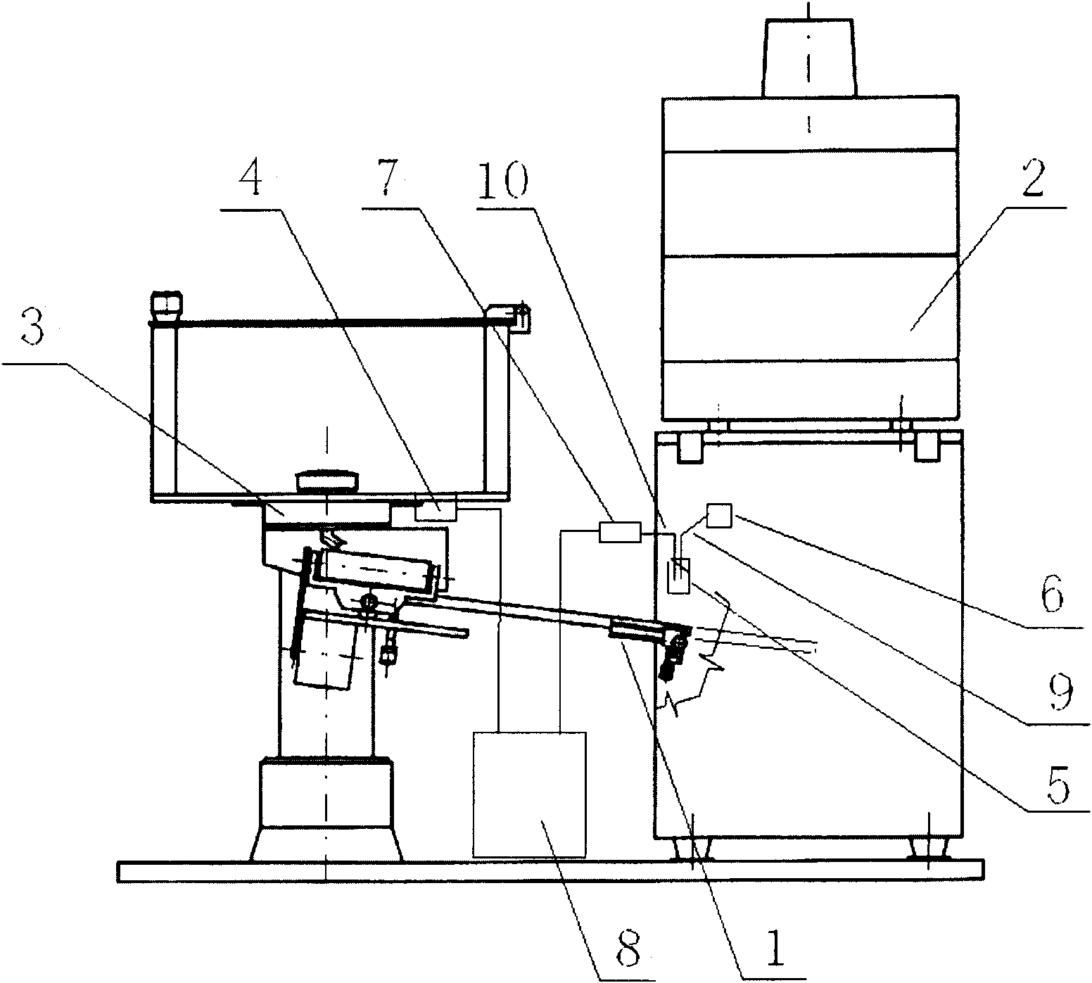
[0007] As shown in the figure, it contains a flow ball bridge 1, an eddy current detection device 2, a ball ejector 3, a ball switch 4, an optical fiber probe 5, a light source 6, a photoelectric amplifier 7, and a programmable controller 8.

[0008] One end of the above-mentioned flow ball bridge 1 is connected with the eddy current detection device 2 and the other end is connected with the ball ejector 3, and the ball ejector 3 is provided with a ball ejection switch 4 that controls and stops the ball ejection. The optical fiber detecting head 5 is arranged above the flow ball bridge 1, and two optical fibers 9 and 10 are respectively connected in the optical fiber detecting head 5, and the optical fibers 9 and 10 are connected to the light source 6 and the photoelectric amplifier 7 respectively.

[0009] The photoelectric amplifier 7 is connected to the programmable controller 8, and the other end of the programmable controller 8 is connected to the ball switch 4. We set the te...


PUM


Abstract

The utility model relates to a flow control device for steel ball flaw detection, which comprises a flowing ball bridge, a vortex detection device, a ball discharging device and a ball discharging switch. One end of the flowing ball bridge is connected with the vortex detection device, the other end of the flowing ball bridge is connected with the ball discharging device, and the ball discharging device is provided with the ball discharging switch; a fiber detection head is arranged above the flowing ball bridge, and the fiber detection head is connected with a light source and a photoelectric amplifier respectively; and the photoelectric amplifier is connected with the ball discharging switch through a programmable controller. The fiber detection head is arranged above the flowing ball bridge, the programmable controller does not work under normal flow rate, steel balls are accumulated on the flowing ball bridge when the flow rate is high, the time for transmitting signals to the programmable controller by the fiber detection head is over a preset time, and the programmable controller controls the ball discharging switch to close so as to stop discharging the balls. By adopting the control device, the steel balls are not magnetized, the subsequent milling and cleaning are not influenced, the working efficiency is indirectly improved, and the power consumption of the fiber detection head is extremely little.

Description

Technical field [0001] The invention relates to a flaw detection steel ball detection flow control device, which comprises a flow ball bridge, an eddy current detection device and a ball ejector. One end of the flow ball bridge is connected with the ball ejector and the other end is connected with the eddy current detection device. Background technique [0002] Steel balls are widely used in various high-precision products, and their surface quality and material determine the service life and safety and reliability of the products, so strict quality inspections must be carried out on steel balls. When detecting steel balls, the steel balls flow out from the ball ejector and enter the eddy current detection device through the flow ball bridge. Due to the limited number of steel balls detected by the eddy current detection device each time, the flow rate is too fast, the steel balls are easy to overflow, the flow rate is too slow, and the detection efficiency is low, so we need to ...

Claims


Application Information

Patent Timeline
Patent Type & Authority Applications(China)
IPC IPC(8): G05D7/06
Inventor 魏正东王嵘沙小建马林于昌梅
Owner JIANGSU LIXING GENERAL STEEL BALL
Learn More