
Method and device for dynamic compensation and pulse compression of higher harmonics intrinsic chirp

A high-order harmonic and pulse compression technology, used in laser parts, instruments, electrical components, etc., can solve the problems of difficult operation, limited chirped compensation spectral range, difficult chirped mirror manufacturing process, etc., to improve the production efficiency. Effect

Inactive Publication Date: 2010-08-25
SHANGHAI INST OF OPTICS & FINE MECHANICS CHINESE ACAD OF SCI
View PDF1 Cites 0 Cited by
  • Summary
  • Abstract
  • Description
  • Claims
  • Application Information

AI Technical Summary

Problems solved by technology

The former is difficult to operate in the experiment due to the high manufacturing process of the chirped mirror in the X-ray band, and the latter depends on the dispersion characteristics of the transmission medium. It is inevitable that the medium provides dispersion compensation and has certain effects on harmonic radiation. Absorption loss, which requires a balance between the negative group velocity dispersion and absorption loss that the medium can provide, so this limits the spectral range for chirp compensation
In addition, the above-mentioned methods are all based on the dispersion characteristics of materials. Most materials in the extreme ultraviolet band have negative dispersion characteristics. So far, only the compensation of positive chirp has been achieved experimentally.
Compensation for negative chirp of XUV band attosecond pulses is extremely difficult due to the need to find suitable materials with positive group velocity dispersion

Method used


Image

  • Method and device for dynamic compensation and pulse compression of higher harmonics intrinsic chirp
  • Method and device for dynamic compensation and pulse compression of higher harmonics intrinsic chirp
  • Method and device for dynamic compensation and pulse compression of higher harmonics intrinsic chirp

Examples


Embodiment Construction

[0027] The present invention will be further described below in conjunction with the accompanying drawings and embodiments.

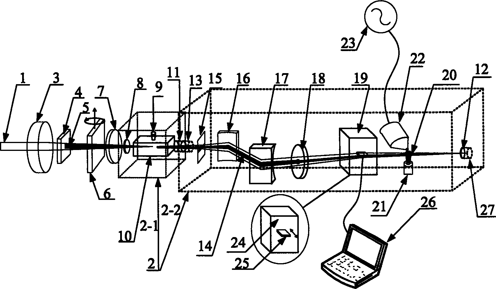
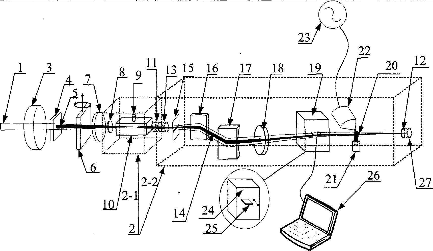
[0028] Please refer to FIG. 1 . FIG. 1 is a schematic structural diagram of a device for dynamic compensation and pulse compression of high-order harmonic inherent chirp according to the present invention. As can be seen from the figure, the device for dynamic compensation and pulse compression of high-order harmonic inherent chirp of the present invention includes a converging lens 3, a BBO frequency doubling crystal 4, a time delay plate 6, A dual-band wave plate 7 and a high-order harmonic generation cavity 2-1, the high-order harmonic generation cavity 2-1 has an input window 8 and an output port 11, and the vacuum degree of the high-order harmonic generation cavity 2-1 is up to 10 -2 Above Pa, a gas box 10 is set in the high-order harmonic generation cavity 2-1, and the gas box 10 is filled with a first inert gas 9, which passes through the output...


PUM

PropertyMeasurementUnit
thicknessaaaaaaaaaa
widthaaaaaaaaaa
thicknessaaaaaaaaaa

Abstract

A method and a device for dynamic compensation and pulse compression of higher harmonics intrinsic chirp are disclosed; in the method, the reshaping function of two colour laser fields on an electric field is used, when a weak frequency multiplication filed is overlapped on fundamental frequency light, the frequency multiplication filed introduces an additional phase item of a sin function form in the generating process of harmonic wave, the additional phase item can change from negative periodicity to positive periodicity along with the relatively delayed alteration between two colour fields, thus causing the chirp compensation of attosecond pulse to continuously change from negative to positive and obtaining the attosecond pulse of change limit. The invention not only can realize the compensation on attosecond pulse chirp but also can improve the generation efficiency of harmonics, and the invention is also suitable for single attosecond pulse below hundred attosecond.

Description

technical field [0001] The invention relates to attosecond pulses, which is a method and device for dynamic compensation and pulse compression of high-order harmonic inherent chirp, capable of performing chirp compensation and pulse compression on attosecond pulses in extreme ultraviolet (XUV) and soft X-ray bands. Compression to obtain transform-limited attosecond pulses. Background technique [0002] High-order harmonic generation and attosecond pulse radiation based on high-order harmonic generation have been extensively and deeply studied in recent years. Among many important applications, the detection of ultrafast electron dynamics with unprecedented precision by attosecond pulses and the generation of frequency combs in the extreme ultraviolet region have attracted great attention. These applications determine that one of the most important goals at present is to obtain attosecond pulses as short as possible. Although there have been many methods to generate attosec...

Claims


Application Information

Patent Timeline
Patent Type & Authority Patents(China)
IPC IPC(8): H01S3/109G02F1/35
Inventor 郑颖辉曾志男邹璞李儒新徐至展
Owner SHANGHAI INST OF OPTICS & FINE MECHANICS CHINESE ACAD OF SCI
Learn More