Phase Control Reactive Power Dynamic Compensation Method

A dynamic compensation and power technology, applied in reactive power compensation, reactive power adjustment/elimination/compensation, electrical components, etc., to achieve good compensation effect, easy dynamic compensation, and accurate compensation

Inactive Publication Date: 2011-12-07
NANNING MICRO CONTROL HIGH TECH
View PDF6 Cites 3 Cited by
  • Summary
  • Abstract
  • Description
  • Claims
  • Application Information

AI Technical Summary

Problems solved by technology

[0005] Static compensation: usually divided into fixed or graded compensation, the general structure is relatively simple, and AC contactors are mostly used as switching actuators for power capacitors, but there are disadvantages When the compensation capacitor is switched, the impact current is large, the switching speed is slow, and the failure rate of the contactor is high due to frequent switching

Method used


Image

  • Phase Control Reactive Power Dynamic Compensation Method
  • Phase Control Reactive Power Dynamic Compensation Method
  • Phase Control Reactive Power Dynamic Compensation Method

Examples


Embodiment Construction

[0040] The phase-controlled reactive power dynamic compensation device and the reactive power compensation method of the present invention will be further described below in conjunction with the accompanying drawings.

[0041] Description of the principle of reactive power compensation in the present invention:

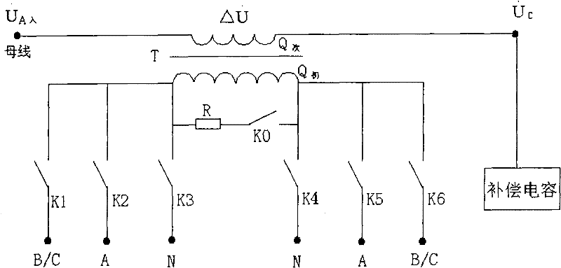
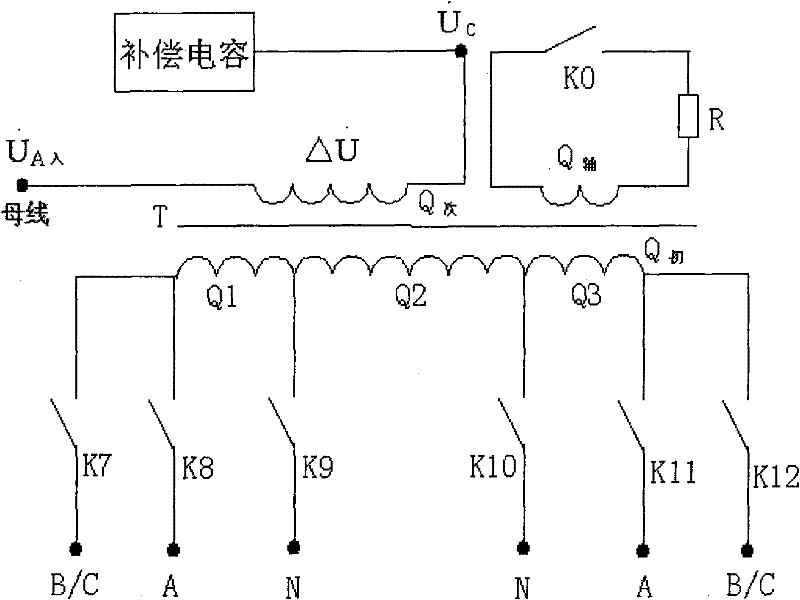
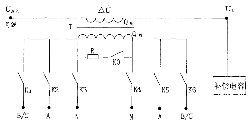
[0042] refer to figure 1 . Let the voltage connected to the bus be The voltage across the secondary winding of the compensation transformer is The voltage across the compensation capacitor is Then the relationship between the three is:

[0043] The reactive power emitted by the compensation capacitor is: Q = 3 U C I C = 3 U C 2 / X C , Then by adjusting U C The amount of reactive power compensat...


PUM


Abstract

The invention discloses a phase-controlled reactive power dynamic compensation device and a compensation method thereof. The device includes a control and detection circuit, a compensation capacitor, and a compensation transformer; the secondary winding of the compensation transformer is connected to the bus bar after being connected in series with the capacitor, and the two ends of the primary winding are respectively connected to different phase lines or neutral lines of the bus bar through several selection switches ;By controlling the on-off of the selector switch, the primary winding is selectively applied with the same phase voltage, out-of-phase phase voltage, or line voltage connected to the secondary winding; the combination of the multiple selector switches forms multiple compensation gears bit. This device comprehensively applies out-of-phase phase voltage, in-phase phase voltage and line voltage on the input coil of the primary winding of the compensation transformer, and adjusts the transformation ratio to compensate the secondary output. The structure is simple but it is easy to realize dynamic compensation. High efficiency and good compensation effect. The compensation device and method of the present invention are applicable to all voltage levels of the existing power grid and various occasions such as substations and electrified railways.

Description

technical field [0001] The invention relates to a reactive power compensation method and a reactive power compensation device, more specifically, to a phase-controlled reactive power dynamic compensation device and a compensation method thereof. Background technique [0002] In the distribution network, the reactive power generated by the power generator and the power of the transmission line are often insufficient to meet the reactive power demand of a large number of motors, transformers, reactors, fluorescent lamps and other inductive loads in the network and the reactive power loss in the system. , which often leads to a decrease in the power factor of the grid and a decrease in the utilization rate of the grid system. In order to reduce active power loss and voltage drop, reduce loss in power transmission, ensure safe, economical and efficient operation of the power grid, and improve the capacity and quality of power transmission, it is usually necessary to perform nea...

Claims


Application Information

Patent Timeline
Patent Type & Authority Patents(China)
IPC IPC(8): H02J3/18H02J3/01H02H7/04
CPCY02E40/30Y02E40/40
Inventor 骆武宁海涛
Owner NANNING MICRO CONTROL HIGH TECH
Why Eureka
Try Eureka