Modulation method applied to cascade converter
A modulation method and converter technology, applied in the direction of converting irreversible DC power input into AC power output, can solve the problems of large amount of calculation, easy long-term work fatigue of the device, and no consideration of the working condition of the device, and achieves simple writing. , the effect of simplifying the judgment time
Inactive Publication Date: 2011-02-09
SOUTHEAST UNIV
View PDF0 Cites 0 Cited by
- Summary
- Abstract
- Description
- Claims
- Application Information
AI Technical Summary
Problems solved by technology
The existing multi-level space vector modulation technology for voltage source converters requires a large amount of calculation to determine the area and action time of the vector, and the action time of each power unit switching device of the device is not equal, that is, some devices are prone to long-term Work fatigue and some devices only work for a short time, without considering the actual working conditions of the devices
Method used
View moreImage
Smart ImageViewing Examples
Examples
Embodiment Construction
Login to View More PUM
 Abstract
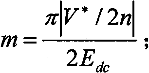
The invention provides a modulation method applied to a cascade converter, which comprises the following steps: obtaining a linear modulation region, a first over-modulation region and a second over-modulation region according to the direct current voltage value, the control command reference voltage vector and the power unit number of each phase of a bridge voltage source type power unit; and setting Edc as the direct current voltage value of the bridge voltage source type power unit, V<*> as the control command reference voltage vector, and n as the power unit number of each phase so that the modulation ratio m is equal to (pi|V<*> / 2n|) / 2Edc, wherein the interval that m is more than or equal to 0 and less than or equal to 0.906 is the linear modulation region, the interval that m is more than or equal to 0.906 and less than or equal to 0.951 is the first over-modulation region, and the interval that m is more than or equal to 0.951 and less than or equal to 1 is the second over-modulation region. The modulation method can simplify the judgment time of the vector areas.
Description
technical field The invention relates to a modulation method applied to cascaded converters, in particular to a modulation method using space vector pulse width modulation (SVPWM) technology. Background technique Sine wave pulse width modulation (SPWM) and space vector pulse width modulation (SVPWM) are two basic modulation methods of voltage source converters, but because SVPWM is closely integrated with motor flux linkage control, it is convenient for digital implementation and DC voltage The utilization rate is high, so SVPWM is more widely used in motor speed regulation than SPWM. In recent years, with the needs of the industry, the topology of the converter has gradually developed from the original low-voltage bridge converter to a variety of high-voltage, large-capacity and multi-voltage converters such as diode clamps, flying capacitor clamps, and cascaded structures. flat way. In large-capacity converters, the cascaded structure uses lower withstand voltage devices...
Claims
Login to View More Application Information
Patent Timeline
 Patent Type & Authority Patents(China)
IPC IPC(8): H02M7/48
Inventor 赵剑锋倪喜军郑良广孙仪闫安心
Owner SOUTHEAST UNIV
Features
- R&D
- Intellectual Property
- Life Sciences
- Materials
- Tech Scout
- Unparalleled Data Quality
- Higher Quality Content
- 60% Fewer Hallucinations
Learn More Browse by: Latest US Patents, China's latest patents, Technical Efficacy Thesaurus, Application Domain, Technology Topic, Popular Technical Reports.
© 2025 PatSnap. All rights reserved.Legal|Privacy policy|Modern Slavery Act Transparency Statement|Sitemap|About US| Contact US: help@patsnap.com


