Field system

A technology of excitation system and magnetic pole face, applied in the direction of magnetic circuit, magnetic circuit rotating parts, magnetic circuit static parts, etc., can solve the problems of reduced productivity, unable to insert unit magnets, etc., to reduce the necessary accuracy and improve the interlinkage. Magnetic flux, effect of reducing manufacturing cost

Active Publication Date: 2009-12-30
DAIKIN IND LTD
View PDF2 Cites 9 Cited by
  • Summary
  • Abstract
  • Description
  • Claims
  • Application Information

AI Technical Summary

Problems solved by technology

[0007] However, in the technology described in Patent Document 1, the volume of the insertion hole is several times larger than that of the unit magnet, so when the unit magnet is inserted into the insertion hole, for example, the unit magnet may be inserted into the insertion hole obliquely.
In this case, when the next unit magnet is inserted into the insertion hole, it will interfere with the unit magnet inserted obliquely. As a result, the desired number of unit magnets may not be inserted into the insertion hole.
In turn, resulting in a decrease in productivity

Method used


Image

  • Field system
  • Field system
  • Field system

Examples


no. 1 Embodiment approach

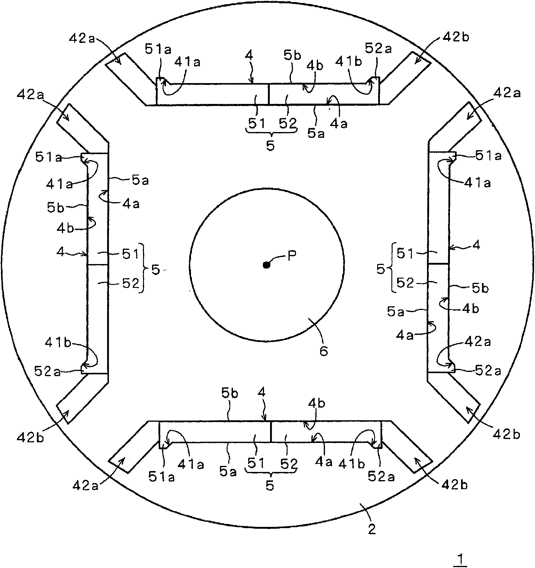
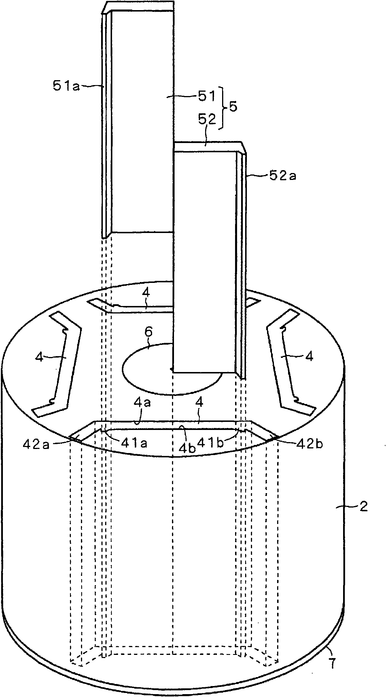
[0040] figure 1 A schematic cross-sectional view showing an excitation system according to a first embodiment of the present invention. figure 1 A schematic configuration of a cross section perpendicular to the rotation axis P of the excitation system 1 is shown. This excitation system 1 has an excitation core 2, a field magnet 5, and an unillustrated end plate.

[0041] Such as figure 1 As shown, the field core 2 has an annular outer periphery centered on the rotation axis P. As shown in FIG. The field core 2 is provided with an insertion hole 4 and a shaft hole 6 . In addition, the field core 2 is made of a magnetic material and extends in a direction parallel to the rotation axis P (direction perpendicular to the paper surface: not shown, hereinafter referred to as the rotation axis direction).

[0042] More specifically, in the field core 2 , a shaft hole 6 is provided in a region including the rotation axis P, and a shaft (not shown) is inserted through the shaft hole...

no. 2 Embodiment approach

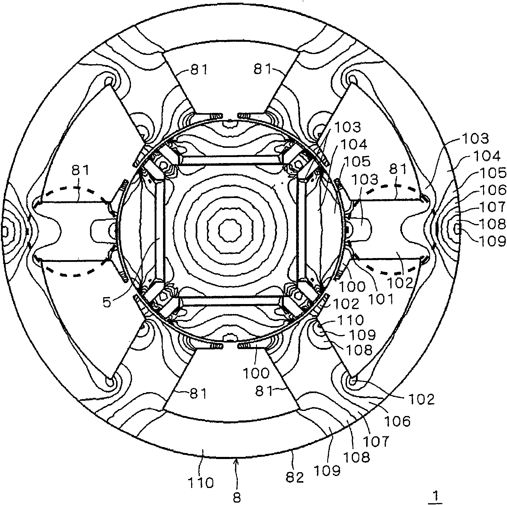
[0069] Figure 13A schematic cross-sectional view showing an excitation system according to a second embodiment of the present invention. Figure 13 A schematic configuration of a cross section perpendicular to the rotation axis P of the excitation system 1 is shown. The exciter system 1 has an exciter core 2 and a field magnet 5 .

[0070] Figure 13 Excitation system 1 shown with figure 1 The exciter system 1 shown differs in that the field magnet 5 is formed by a permanent magnet.

[0071] According to this excitation system 1, the same as used in the first embodiment Figure 3-6 The description is the same, and it is possible to improve the field magnetic flux and the anti-demagnetization force. Furthermore, similarly to the first embodiment, the insertion surfaces 4a, 4b and the magnetic pole surfaces 5a, 5b function as guides for guiding the field magnet 5, so the field magnet 5 can be easily inserted into the insertion hole 4.


PUM


Abstract

The present invention relates to a field element which has high productivity. A field element (1) includes a field core (2) and a field magnet (5). The field magnet (5) is formed of, for example, two permanent magnets (51, 52), and a width of the field magnet (5) increases from a center toward both ends thereof in a monotonically non-decreasing manner. The field magnet (5) includes, at the both ends thereof, projecting portions (51a, 52a) projecting to a side opposite to a rotation axis (P). The field core (2) includes a penetration hole (4) through which the field magnet (5) is caused to penetrate. The penetration hole (4) includes penetration surfaces (4a, 4b) which cover magnetic pole surfaces (5a, 5b) of the field magnet (5), respectively. Specifically, the penetration surface (4b) includes concave portions (41a, 41b) with which the projecting portions (51a, 52a) are fitted. When the field magnet (5) is inserted, the penetration surfaces (4a, 4b) serve as a guide which guides the field magnet (5), and accordingly the field magnet (5) can be caused to penetrate through the penetration hole (4) with ease.

Description

technical field [0001] The invention relates to an excitation system, in particular to an embedded excitation system. Background technique [0002] Patent Document 1 discloses a rotor in which permanent magnets composed of a plurality of unit magnets are inserted into insertion holes. [0003] In addition, Patent Document 2 and Patent Document 3 disclose techniques related to the present invention. [0004] Patent Document 1: Japanese Patent No. 3690067 [0005] Patent Document 2: Japanese Patent Laid-Open No. 2005-261169 [0006] Patent Document 3: Japanese Patent Laid-Open No. 2004-328963 [0007] However, in the technology described in Patent Document 1, the volume of the insertion hole is several times larger than that of the unit magnet. Therefore, when the unit magnet is inserted into the insertion hole, for example, the unit magnet may be inserted into the insertion hole obliquely. In this case, when the next unit magnet is inserted into the insertion hole, it int...

Claims


Application Information

Patent Timeline
Patent Type & Authority Applications(China)
IPC IPC(8): H02K1/27
CPCH02K1/276H02K1/14H02K15/03
Inventor 青田桂治浅野能成
Owner DAIKIN IND LTD
Why Eureka
Try Eureka