Method and device for improving operation comfort of excavator

A comfort and excavator technology, applied in the direction of mechanically driven excavators/dredgers, etc., can solve the problems of affecting the working efficiency, affecting the working quality, and increasing fatigue of excavators, so as to improve the operating comfort and stability , The effect of slowing down the oil return speed

Inactive Publication Date: 2010-01-06
SANY HEAVY MACHINERY
View PDF0 Cites 14 Cited by
  • Summary
  • Abstract
  • Description
  • Claims
  • Application Information

AI Technical Summary

Problems solved by technology

However, during this series of operations, due to the speed of oil supply and oil return is too fast, when the fuselage changes operations, there will be a large acceleration, and there will be discomfort such as shaking, noise or shaking as a whole. For operators who work in such an environment for a long time, it is quite uncomfortable, which increases fatigue and affects the quality of work; if the flow rate of the oil circuit is directly reduced and the flow rate is limited, the impact can be reduced, but it is bound to Affect the working efficiency of the excavator

Method used


Image

  • Method and device for improving operation comfort of excavator
  • Method and device for improving operation comfort of excavator
  • Method and device for improving operation comfort of excavator

Examples


Embodiment 1

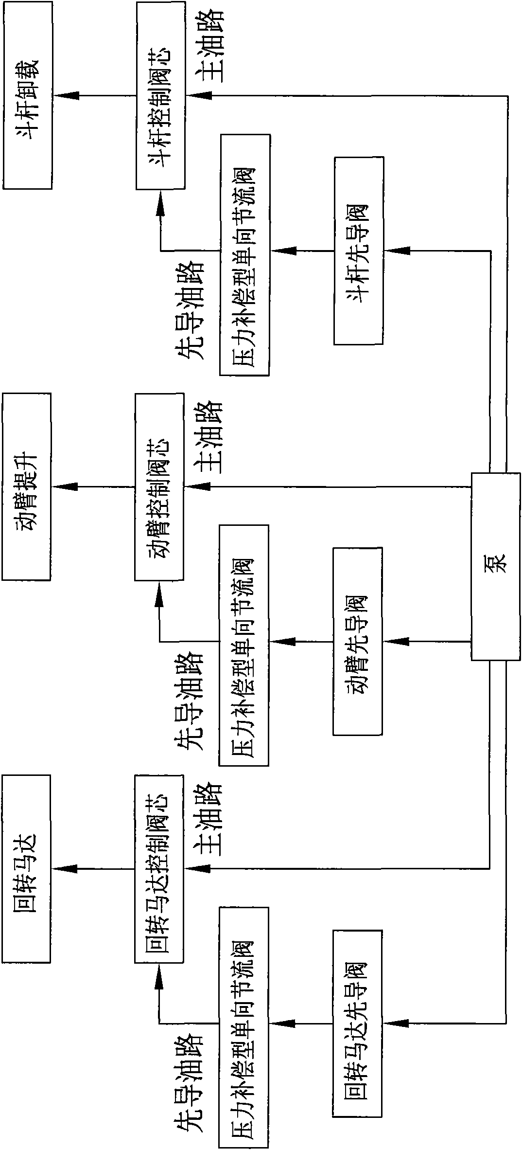
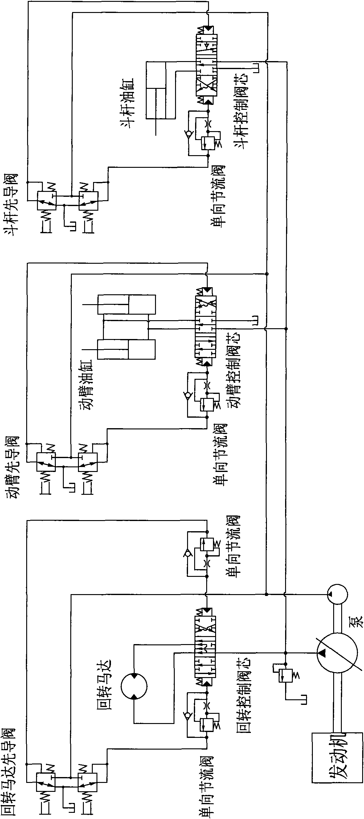
[0025] Example 1: see Figure 1 to Figure 2 As shown, a method and device for improving the operating comfort of an excavator are provided with a one-way throttle valve at each end of the pilot oil path of the swing control spool, and a small cavity end in the pilot oil path of the boom control spool. A one-way throttle valve is set, and a one-way throttle valve is set at the unloading end of the pilot oil circuit of the stick control spool; the one-way throttle valve has the function of pressure compensation, and is composed of a one-way valve, a throttle A valve and a pressure reducing valve are combined, the throttle valve and the pressure reducing valve are connected in series, the two ends of the one-way valve are respectively connected in parallel to the input end of the throttle valve and the output end of the pressure reducing valve. The input end is located on the side of the corresponding pilot valve, and the output end is located on the side of the corresponding mai...

Embodiment 2

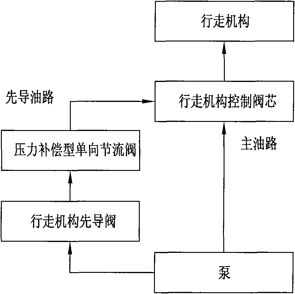
[0027] Example 2: see image 3 , 4 As shown in the figure, a method and device for improving the operating comfort of an excavator are provided with a one-way throttle valve at each end of the pilot oil path of the swing control spool, and pilot oil is provided in the control spool of the boom, stick and bucket. A one-way throttle valve is respectively set at both ends of the road, and a one-way throttle valve is respectively set at both ends of the pilot oil circuit of the traveling mechanism control spool; A one-way valve, a throttle valve and a pressure reducing valve are combined, the throttle valve and the pressure reducing valve are connected in series, and the two ends of the one-way valve are respectively connected in parallel to the input end of the throttle valve and the pressure reducing valve. On the output end, the input end of the check valve is located on the side of the corresponding pilot valve, and the output end is located on the side of the corresponding m...


PUM


Abstract

The invention discloses a method and a device for improving the operation comfort of an excavator. The device is characterized in that a one-way throttle valve is additionally arranged at one end or both ends of a pilot oil line of a revolving control valve core and a movable arm control valve core; when pilot oil flows to a main control valve core from a corresponding pilot valve, the single throttle valve on the branch is in an opened state; when the pilot oil flows to the corresponding pilot valve from the main control valve core, the one-way throttle valve on the branch is in a closed state, and the pilot oil returns through throttle holes of the one-way throttle valve. By arranging the one-way throttle valve on the pilot oil of the revolving control valve core and the movable arm control valve core, the oil returning speed is limited, and the hydraulic impact is reduced, thus the operation comfort is enhanced.

Description

technical field [0001] The present invention relates to a control method and device of an excavator, in particular to a method and device capable of improving the operating comfort of an excavator. Background technique [0002] Hydraulic excavators are widely used in building foundation excavation and cleaning after completion, urban pipeline laying, farmland water conservancy construction and other occasions, with the advantages of flexible construction and high efficiency. Generally, it is composed of working device, slewing device, traveling device and hydraulic control device. The working device is a device that directly completes the excavation task. The extension and retraction of the stick, the rotation of the bucket and the rotation of the slewing device are all realized by the control device through the hydraulic circuit to control the oil supply of each hydraulic pump. When excavating at a construction site, excavators are usually used for a long time. Therefore,...

Claims


Application Information

Patent Timeline
Patent Type & Authority Applications(China)
IPC IPC(8): E02F3/42
Inventor 戴晴华陈克雷肖飞
Owner SANY HEAVY MACHINERY
Why Eureka
Try Eureka