
Head-light structure of motive bicycle

A technology for two-wheeled motor vehicles and headlights, which is applied in the directions of motor vehicles, lamp shades, road vehicles, etc., to achieve the effects of improving the charm of commodities, increasing the amount of light diffusion, and expanding the irradiation range.

Inactive Publication Date: 2010-01-06
HONDA MOTOR CO LTD
View PDF0 Cites 3 Cited by
  • Summary
  • Abstract
  • Description
  • Claims
  • Application Information

AI Technical Summary

Problems solved by technology

[0008] Therefore, it is difficult for the headlight device 50 to give a new impression of left-right asymmetry.

Method used


Image

  • Head-light structure of motive bicycle
  • Head-light structure of motive bicycle
  • Head-light structure of motive bicycle

Examples


Embodiment Construction

[0074] Hereinafter, the best mode for carrying out the present invention will be described based on the drawings. In addition, the drawings are those seen in the direction indicated by the reference numerals.

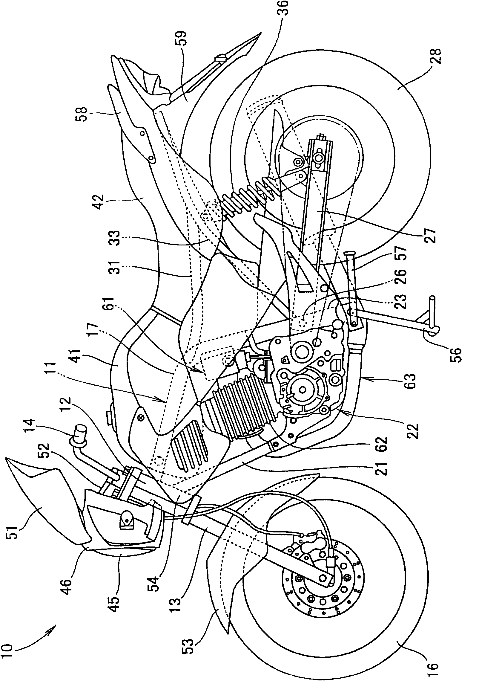
[0075] figure 1 It is a side view of a motorcycle having the headlamp structure of the present invention. The motorcycle 10 is a vehicle in which a front fork 13 is mounted on a head pipe 12 provided at the front end of a vehicle frame 11 in a freely steerable manner. The steering handle 14 is attached to the upper end of the front fork 13, the front wheel 16 is attached to the lower end, and the engine 22 is attached to a pair of left and right main frames 17, 18 (only the reference numeral 17 on the front side) constituting the vehicle frame 11 and the lower frame. On 21, rocking arm 27 swings up and down via pivot 26 and is installed on the pivot frame 23,24 (only shows the reference sign 23 of the front side) that is integrally arranged on main frame 17,18 rear bo...


PUM


Abstract

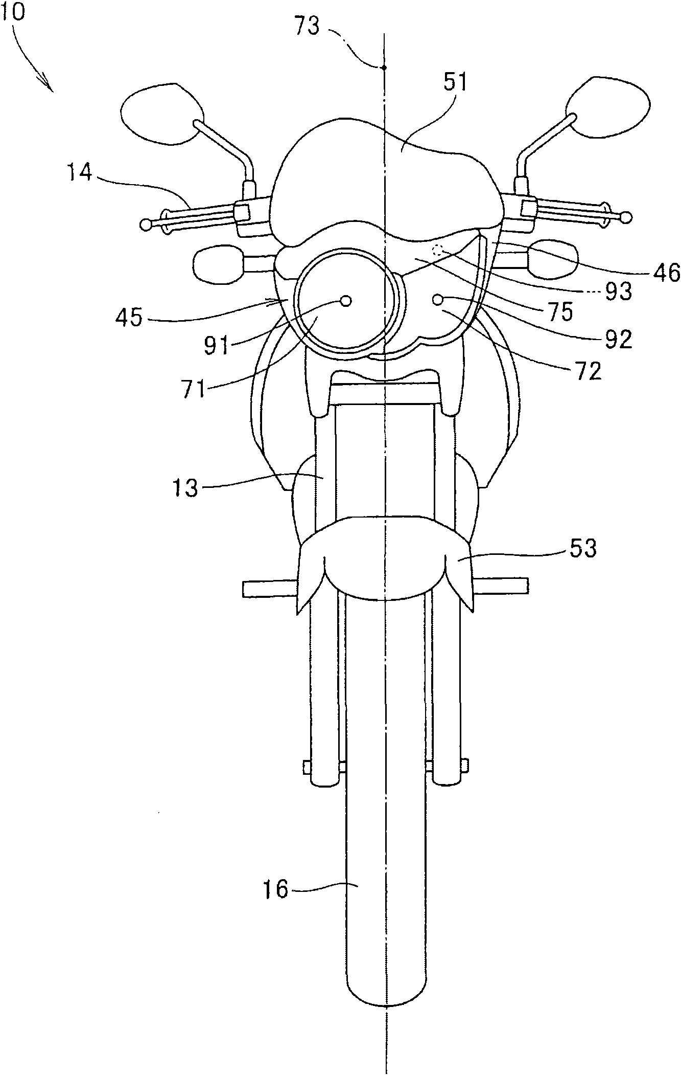
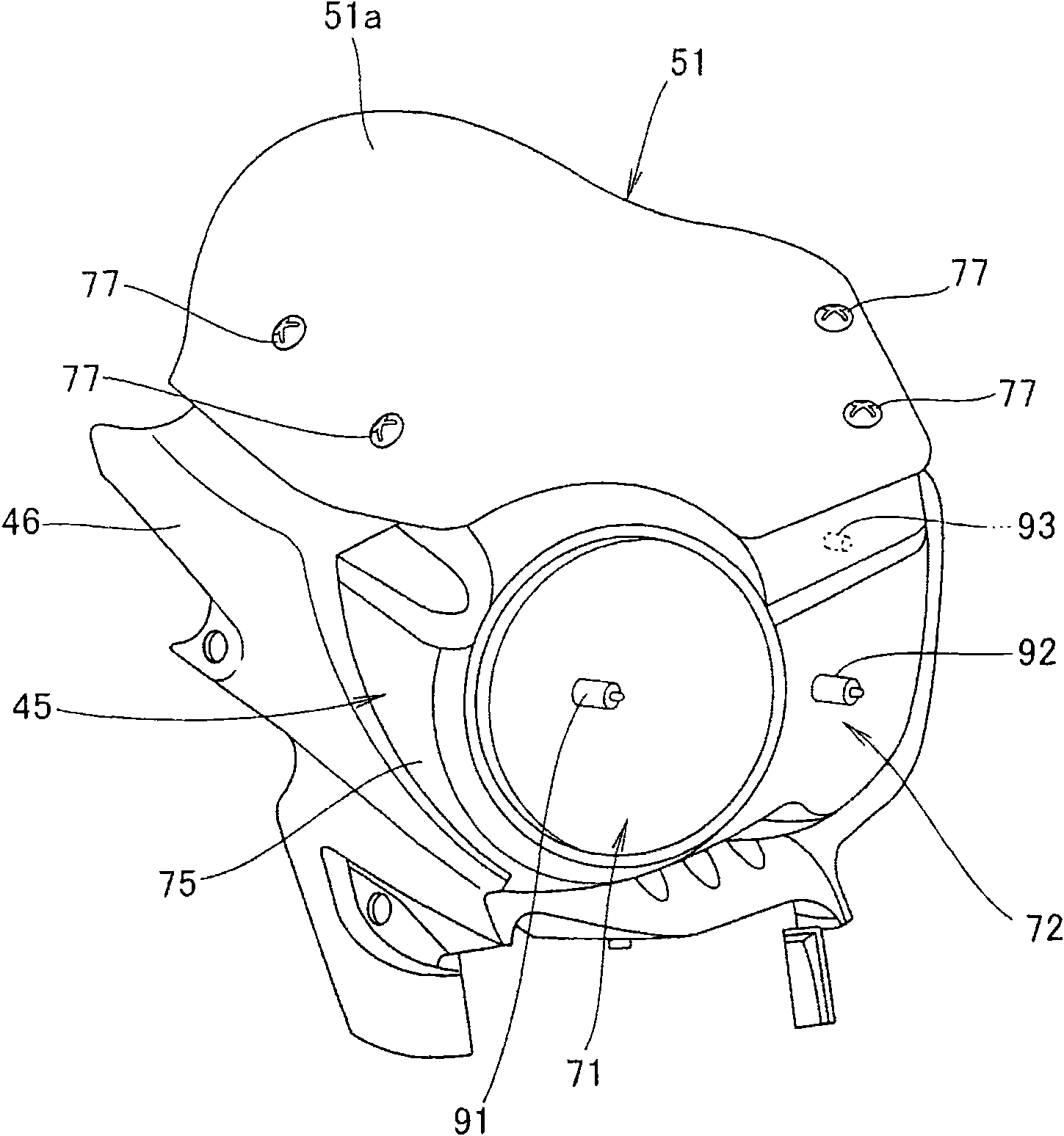
The present invention provides a head-light structure of a motive bicycle, capable of trying for improvement of design and functional properties. When viewing from the frontispiece, the head-light structure of the motive bicycle is provided with at least a near light special lamp (71) and a distance light special lamp (72) on right and left separately, and the right and left near light special lamp (71), distance light special lamp (72) are non symmetrical, wherein a top-to-bottom width (H1) of the near light special lamp (71) is larger than a top-to-bottom width (H2) of the distance light special lamp (72) through a first plumb line (101) of a near light bulb (91) of the near light special lamp (71) and a second plumb line (102) of a distance light bulb (92) of the distance light speciallamp (72), the shapes of the right and left near light special lamp (71) and distance light special lamp (72) form a roundness, and the other is a rectilinear shape.

Description

technical field [0001] The present invention relates to an improvement in the structure of a headlight of a motorcycle. Background technique [0002] The headlight of a motorcycle is a component that has a large influence on determining the design of the vehicle, and is highly important as an exterior component. [0003] As a headlight structure of such a conventional motorcycle, a left-right asymmetrical headlight is known (for example, refer to patent document 1). [0004] Patent Document 1: Japanese Patent No. 3866383 [0005] By patent document 1 Figure 5 It can be seen that the headlamp device 50 is configured such that the discharge lamp 55 is arranged on the left side and the incandescent lamp 59 is arranged on the right side, and the boundary between the discharge lamp 55 and the incandescent lamp 59 is shifted from the center M4 of the vehicle body by only a distance δ4 to form left-right asymmetry. . [0006] In the headlight device 50 , both the discharge lamp...

Claims


Application Information

Patent Timeline
IPC IPC(8): F21S8/10F21V3/00F21V13/04B62J6/02F21W101/027F21W107/17
Inventor 安藤雅晴福拉德杰·福卢昂威德·乔克苏瓦塔纳萨库尔
Owner HONDA MOTOR CO LTD
Learn More