Laser gyro temperature compensation and control device and application
A laser gyro and temperature compensation technology, applied in temperature control, non-electric variable control, control/regulation system, etc., can solve the problems of laser gyro temperature alignment and zero deviation exceeding the standard, and achieve enhanced anti-electromagnetic interference ability, convenient operation, The effect of the obvious compensation effect
- Summary
- Abstract
- Description
- Claims
- Application Information
AI Technical Summary
Problems solved by technology
Method used
Image
Examples
Embodiment 1
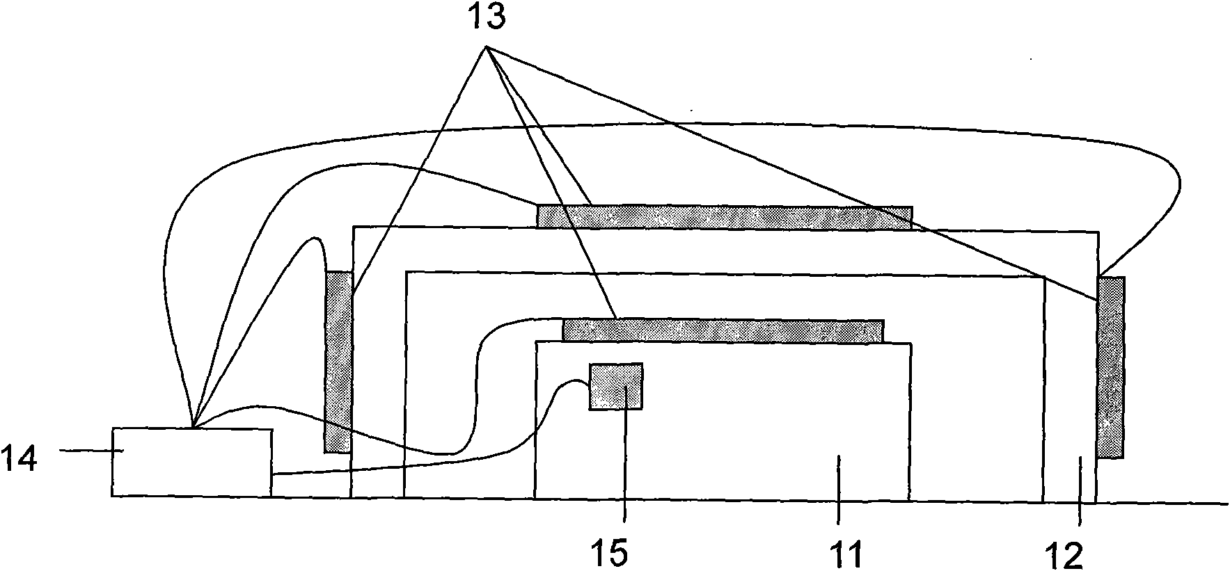
[0019] Example 1: figure 1 It is a structure diagram of a laser gyro temperature compensation control device for cavity surface temperature compensation control, mainly including a laser gyro cavity 11 (available in the market), a metal shell 12, and a temperature control device 13 (such as a semiconductor temperature controller 13, a semiconductor temperature controller, etc.) Any type of controller 13 can be purchased in the market), adaptive temperature control circuit 14 (any type of adaptive temperature control circuit 14 can be purchased in the market) and temperature sensor 15 (any type of temperature sensor 15 can be purchased). The market is composed of purchases). Paste the temperature control device 13 on the surface of the laser gyro cavity 11 or the outer metal shell 12 shell (by mechanical extrusion or adhesive fixing, usually coated with thermal conductive silicone grease between the two contact surfaces), and place the The temperature control device 13 is atta...
Embodiment 2
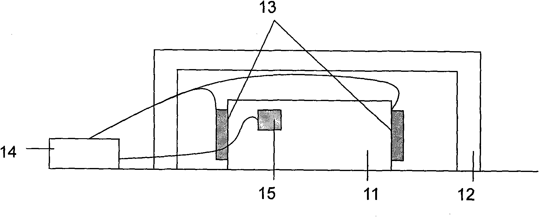
[0021] Example 2: figure 2 It is a structural diagram of a laser gyro temperature compensation control device for cavity branch temperature compensation control, mainly including a laser gyro cavity 11, a metal shell 12, a temperature control device 13 (such as a semiconductor temperature controller), an adaptive temperature control circuit 14 and temperature sensor 15. Stick the temperature control device 13 on the two sides of the laser gyro cavity 11, and place the temperature sensor 15 on the laser gyro cavity 11. When the laser gyro is working at an abnormal temperature state, the temperature sensor 15 will measure the actual temperature of the gyro. Detected and transmitted to the adaptive temperature control circuit 14, the adaptive temperature control circuit 14 provides a certain temperature control power output to load on the temperature control device 13 according to this temperature, and the temperature control device 13 in operation supplies power to the chambers...
Embodiment 3
[0022] Embodiment 3: The application of a temperature control device in laser gyro temperature compensation, the process is to paste the temperature control device 13 on the surface of the laser gyro cavity 11, the branches on both sides or the outer metal shell 12, By heating or cooling the temperature control device 13, the temperature of the laser gyro cavity 11 at abnormal temperature is controlled within the temperature range that can work normally, so as to prevent the temperature of the laser gyro from exceeding the zero deviation, and solve the problem of laser gyro in high and low temperature, The use of engineering application problems in harsh working environments such as sudden temperature changes.
PUM
 Abstract
Description
Claims
Application Information
 - R&D
- Intellectual Property
- Life Sciences
- Materials
- Tech Scout
- Unparalleled Data Quality
- Higher Quality Content
- 60% Fewer Hallucinations
Browse by: Latest US Patents, China's latest patents, Technical Efficacy Thesaurus, Application Domain, Technology Topic, Popular Technical Reports.
© 2025 PatSnap. All rights reserved.Legal|Privacy policy|Modern Slavery Act Transparency Statement|Sitemap|About US| Contact US: help@patsnap.com


