Dpf system with venturi exhaust passage devices

Active Publication Date: 2015-12-17
QI BAOHUA
View PDF6 Cites 10 Cited by
  • Summary
  • Abstract
  • Description
  • Claims
  • Application Information

AI Technical Summary

Benefits of technology

[0016]In another embodiment of the present invention, the upstream high pressure exhaust passage is in communication to a fuel injector, and an electrical heater is fluidly connected to the upstream high pressure exhaust passage. A front DOC positioned downstream from the electrical heater is fluidly connected to the low pressure exhaust passage, and a main DOC positioned downstream from the DPF is fluidly connected to the downstream high pressure exhaust passage. When exhaust gas temperature is low, after a DPF regeneration process starts, dosing fuel is released through the fuel injector at a bootstrapping dosing rate and the electrical heater is energized. The dosing fuel together with the exhaust gas passing through the electrical heater is heated above a light-off temperature of the front DOC, where the dosing fuel is oxidized and the exhaust gas and the front DOC is exothermically heated. The heated exhaust gas then enters the main DOC and heats it. When a bed temperature of the main DOC is higher than its light-off temperature, then the electrical heater is de-energized and a normal dosing rate is generated. There is a bootstrapping process in the heating control, since when the DOCs are exothermically heated, the DOC temperatures get higher, and so is the HC conversion efficiency. Higher HC efficiency cause more HC oxidized and more heat is released in the oxidation reactions, resulting in higher DOC temperature. When the heat released by oxidizing dosing fuel is able to sustain the bed temperature of the main DOC, the electrical heating is no longer required, and since only a fraction of exhaust gas passes through the electrical heater, electrical energy required in the heating control is significantly decreased.
[0017]In another embodiment of t

Problems solved by technology

Through the flow-back passage, a higher exhaust flow rate through the DPF can be obtained, which lowers un-uniform distribution of PM, especia

Method used


Image

  • Dpf system with venturi exhaust passage devices
  • Dpf system with venturi exhaust passage devices
  • Dpf system with venturi exhaust passage devices

Examples


Example

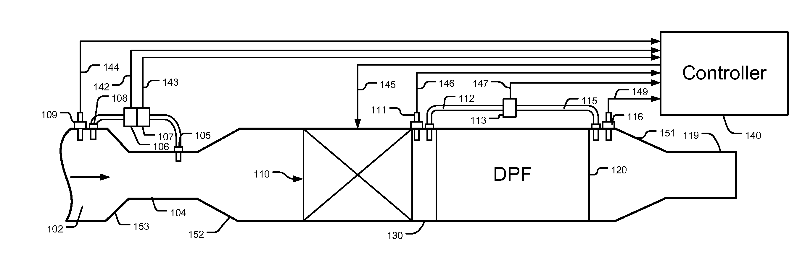
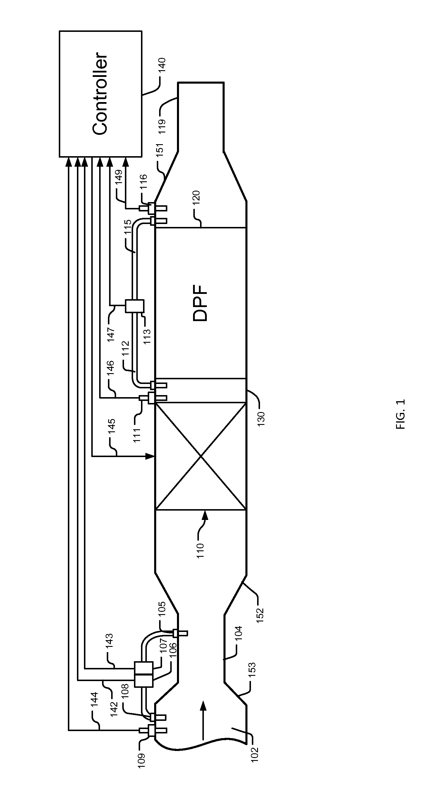
[0027]Referring to FIG. 1, an exhaust passage 102 is fluidly connected to an exhaust passage 104 with a smaller diameter through a cone transition 153. The exhaust passage 104 is fluidly connected to a DPF package 130 through a cone transition 152. Inside the DPF package 130, a heating device 110 is positioned upstream from a DPF 120. On the exhaust passage 102, through a probe 108, a pressure sensor 106, which communicates to a controller 140 through signal lines 142, is used to detect an exhaust gas pressure in the exhaust passage 102, and a differential pressure sensor 107, which is electrically connected to the controller 140 via signal lines 143, is used for measuring a difference between the pressure in the exhaust pipe 102 and that in the exhaust passage 104 through a probe 105 and the probe 108. The exhaust temperature in the exhaust passage 102, in between the heating device 110 and the DPF 120, and downstream from the DPF 120, are sensed, respectively, by temperature senso...


PUM


Abstract

A DPF system including a Venturi exhaust passage device, in which a temperature and a pressure in a high pressure passage are measured, together with a difference of pressures in the high pressure passage and a low pressure passage, while a pressure drop across a DPF is monitored. A PM amount and an exhaust flow rate, which are key parameters in DPF control, can be calculated with the measured values. With the Venturi exhaust passage device, a two-stage bootstrapping heating device with two DOCs and an electrical heater can be used to heat exhaust gas at a temperature lower than a light-off temperature, while a flow-back passage fluidly connected to an outlet of the DPF can be used for increasing exhaust flow-rate and making PM distribution in the DPF more uniform. These technologies decrease risks of thermal runaways, and enable a DPF system controlled without using engine operating parameters.

Description

CROSS-REFERENCE TO RELATED APPLICATIONS[0001]Not ApplicableSTATEMENT REGARDING FEDERALLY SPONSORED RESEARCH OR DEVELOPMENT[0002]Not ApplicableREFERENCE TO SEQUENCE LISTING, A TABLE, OR A COMPUTER PROGRAM LISTING COMPACT DISC APPENDIX[0003]Not ApplicableTECHNICAL FIELD OF THE INVENTION[0004]This present application claims priority from U.S. provisional application No. 62 / 011,734 having the same title as the present invention and filed on Jun. 13, 2014.[0005]This invention relates to an apparatus and method for controlling an exhaust gas processing system for removing particulate matters emitted from an internal combustion engine, more specifically, to an apparatus and method for controlling regenerations of DPFs (Diesel Particulate Filters) in an exhaust gas processing system of an internal combustion engine.BACKGROUND OF THE INVENTION[0006]Environmentally harmful species in exhaust gas emitted from an internal combustion engine, such as hydrocarbons (HC), carbon monoxide (CO), parti...

Claims


Application Information

Patent Timeline
IPC IPC(8): F01N11/00F01N13/00F01N3/025F01N3/029F01N3/023F01N9/00
CPCF01N11/002F01N3/0234F01N9/002F01N2550/04F01N3/0293F01N13/001F01N2550/22F01N3/0253F01N3/027F01N3/2053F01N2410/04Y02T10/40Y02T10/12
Inventor QI, BAOHUA
Owner QI BAOHUA
Why Eureka
Try Eureka