Coupled resonators for timepiece

A technology of a resonator and a second resonator, which is applied in the field of resonators and can solve the problems of the output drop and reliability of the Swiss lever escapement.

Active Publication Date: 2010-01-06
THE SWATCH GRP RES & DEVELONMENT LTD
View PDF1 Cites 36 Cited by
  • Summary
  • Abstract
  • Description
  • Claims
  • Application Information

AI Technical Summary

Problems solved by technology

For high-frequency resonators between 4 and 10 Hz, the transmission ratio becomes very high, but this disadvantage disappears if the number of teeth of the escape wheel is increased
21 teeth is the number quoted for the oscillating frequency of 5

Method used


Image

  • Coupled resonators for timepiece
  • Coupled resonators for timepiece
  • Coupled resonators for timepiece

Examples


no. 1 example

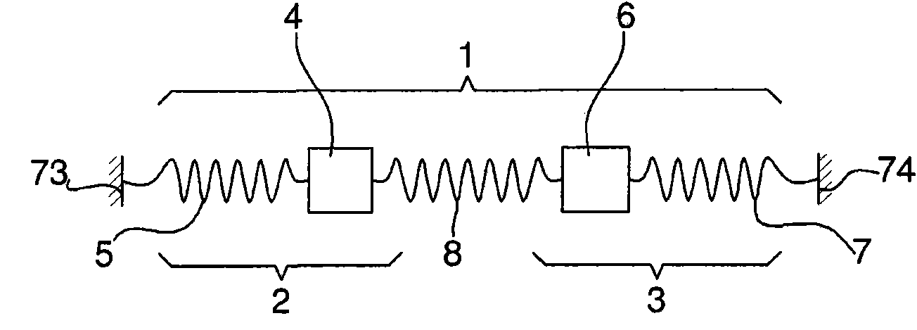
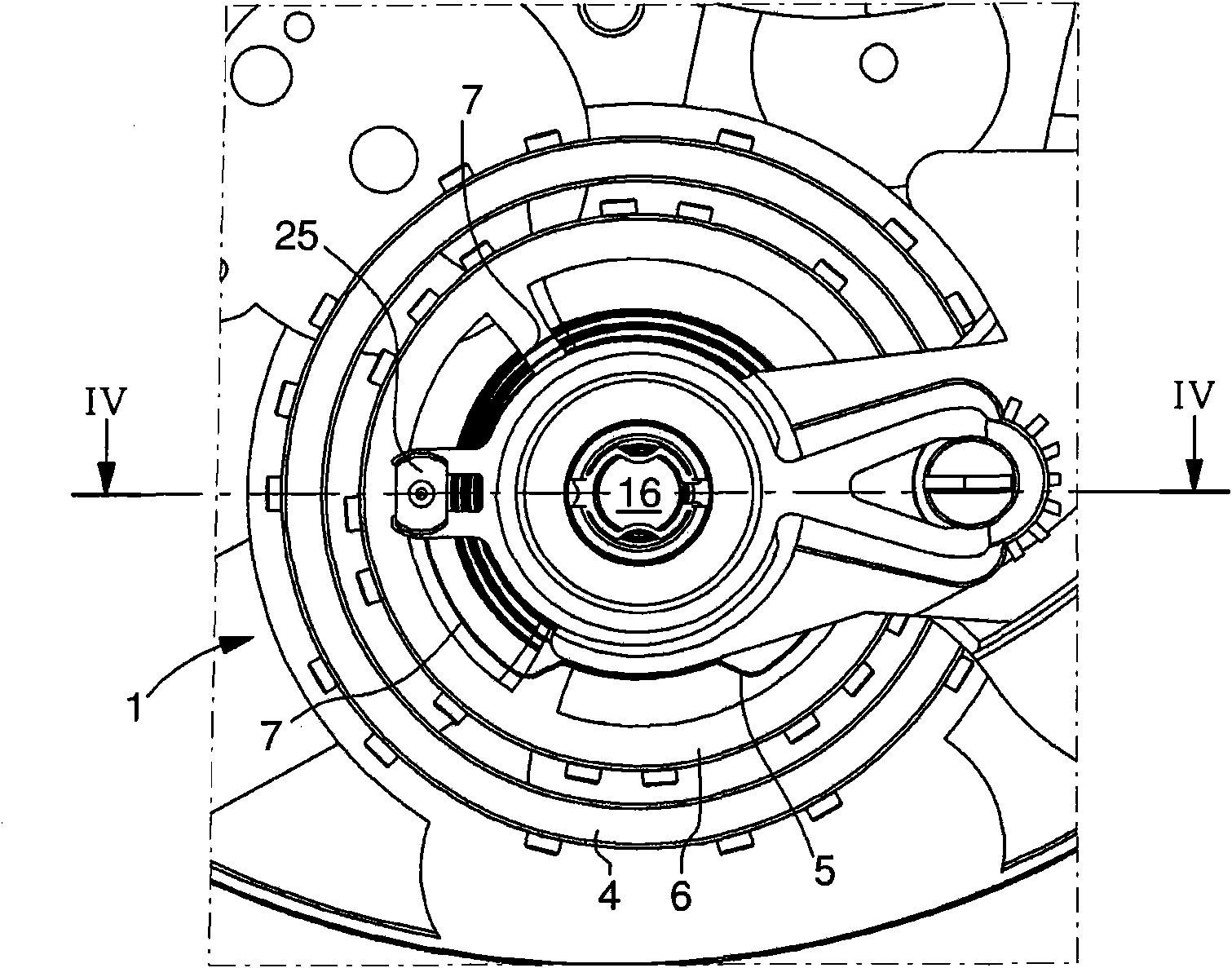
[0028] The resonator 1 made according to the first embodiment of the present invention can refer to figure 2 Equivalence diagram in . Resonator 1 is created by coupling a first resonator 2 and a second resonator 3 . The first resonator 2 comprises a first inertial mass 4 (depicted here as a square mass) with a first balance spring 5 (here depicted as a helical spring) connected at one end to the square mass and at the other end to the The fixed part 73 of the clock, for example connected to the machine plate) is associated. The second resonator 3 comprises a second inertial mass 6 (depicted here as a square mass) with a second balance spring 7 (depicted here as a helical spring) connected at one end to the square mass and at the other end to the The fixed part 74 of clock and watch, for example splint) is associated. A third balance spring 8 , represented here by a helical spring, is arranged between the first inertial mass 4 and the second inertial mass 6 to couple said f...

no. 2 example

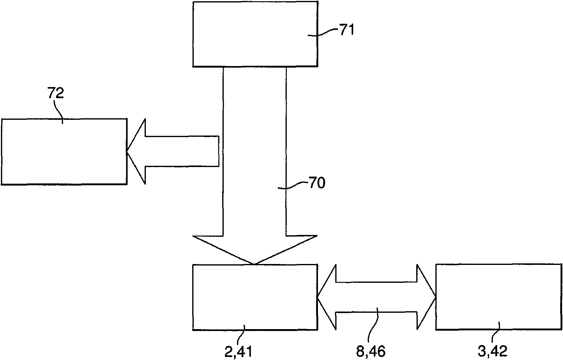
[0054] The resonator 40 made according to the second embodiment of the present invention can refer to Figure 9 Equivalence diagram in . The resonator 40 is produced by coupling a first resonator 41 and a second resonator 42 . The first resonator 41 comprises a first inertial mass 43 (depicted here as a square mass) connected to a first hairspring 44 (here depicted as a helical spring) connected at one end to the square mass and at the other end to the The fixed part 73 of clock and watch, such as machine plate) is associated. The second resonator 42 includes a second inertial mass 45 (depicted here as a square mass) connected to a second balance spring 46 (here depicted as a helical spring) connected at one end to the square mass 43 and at the other end to the to the square mass 45) associated. The second balance spring 46 thus connects the first inertial mass 43 and the second inertial mass 45 to couple said first resonator 41 and second resonator 42 . In fact, balance s...


PUM


Abstract

The resonator (1) for a timepiece results from coupling a first, low frequency resonator (2) with a second, higher frequency resonator (3). The first resonator (2) has a first balance (4) associated with a first balance spring (5). The second resonator (3) has a second balance (6) associated with a second balance spring (7). A third balance spring is arranged between the first (4) and second (6) balances to couple said first (2) and second (3) resonators.

Description

technical field [0001] The present invention relates to a resonator for a watch obtained by coupling (connecting) a first low frequency resonator to a second high frequency resonator. Background technique [0002] EP Patent No. 1843227A1 discloses a resonator according to the above definition. In this document, the first low-frequency resonator is the balance with hairspring and the second high-frequency resonator is the tuning fork. One branch of the tuning fork is connected directly to the outer coil of the balance spring to form the coupling between the two resonators. The purpose of this arrangement is to stabilize the operating frequency of the timepiece, making this frequency more independent of external stresses and ultimately improving the operating accuracy of the timepiece. In the disclosed arrangement the natural frequency of the first resonator is of the order of a few hertz and the frequency of the second resonator is of the order of kilohertz. The design ide...

Claims


Application Information

Patent Timeline
IPC IPC(8): G04B17/06
CPCG04B17/06G04B17/20G04B17/04G04C5/005
Inventor T·赫斯勒K·特鲁姆皮J·-L·赫尔弗T·科努斯
Owner THE SWATCH GRP RES & DEVELONMENT LTD
Why Eureka
Try Eureka