Method and device for winding coils

A technology of a winding device and a winding method, which is applied in the direction of coil manufacturing, etc., can solve the problems of time-consuming and laborious shaping operations, and achieve the effects of improving productivity and shortening production takt time.

Active Publication Date: 2010-01-06
NITTOKU ENG CO LTD
View PDF1 Cites 20 Cited by
  • Summary
  • Abstract
  • Description
  • Claims
  • Application Information

AI Technical Summary

Problems solved by technology

[0006] However, in this conventional coil winding device, since the lead wire portion extending from the coil portion extends in the winding direction (tangential direction) of the coil portion, it is difficult to install When coiling, it is necessary to perform the work of shaping the lead part according to the shape of the substrate, so there is a problem that this shaping work is time-consuming and laborious.

Method used


Image

  • Method and device for winding coils
  • Method and device for winding coils
  • Method and device for winding coils

Examples


Embodiment Construction

[0022] Hereinafter, embodiments of the present invention will be described based on the drawings.

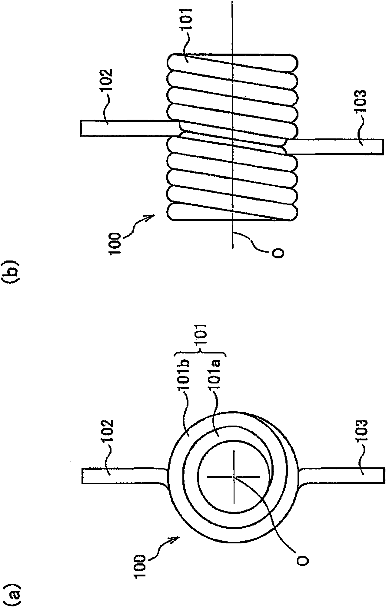
[0023] figure 1 (a) is a side view of the double outer winding coil (coil) 100, and (b) is a front view of the double outer winding coil 100. The double outer winding coil 100 has a coil portion 101 around which the wire 2 is spirally wound, and has a first lead portion 102 and a second lead portion 103 as a lead portion constituted by the wire 2 extending from the coil portion 101 .

[0024] The coil part 101 has the 1st layer winding part 101a and the 2nd winding part 101b. The first lead part 102 and the second lead part 103 are shaped such that they are respectively bent from the second-layer winding part 101b of the coil part 101, and extend from the winding center axis O in a radial direction with an angular difference of 180°.

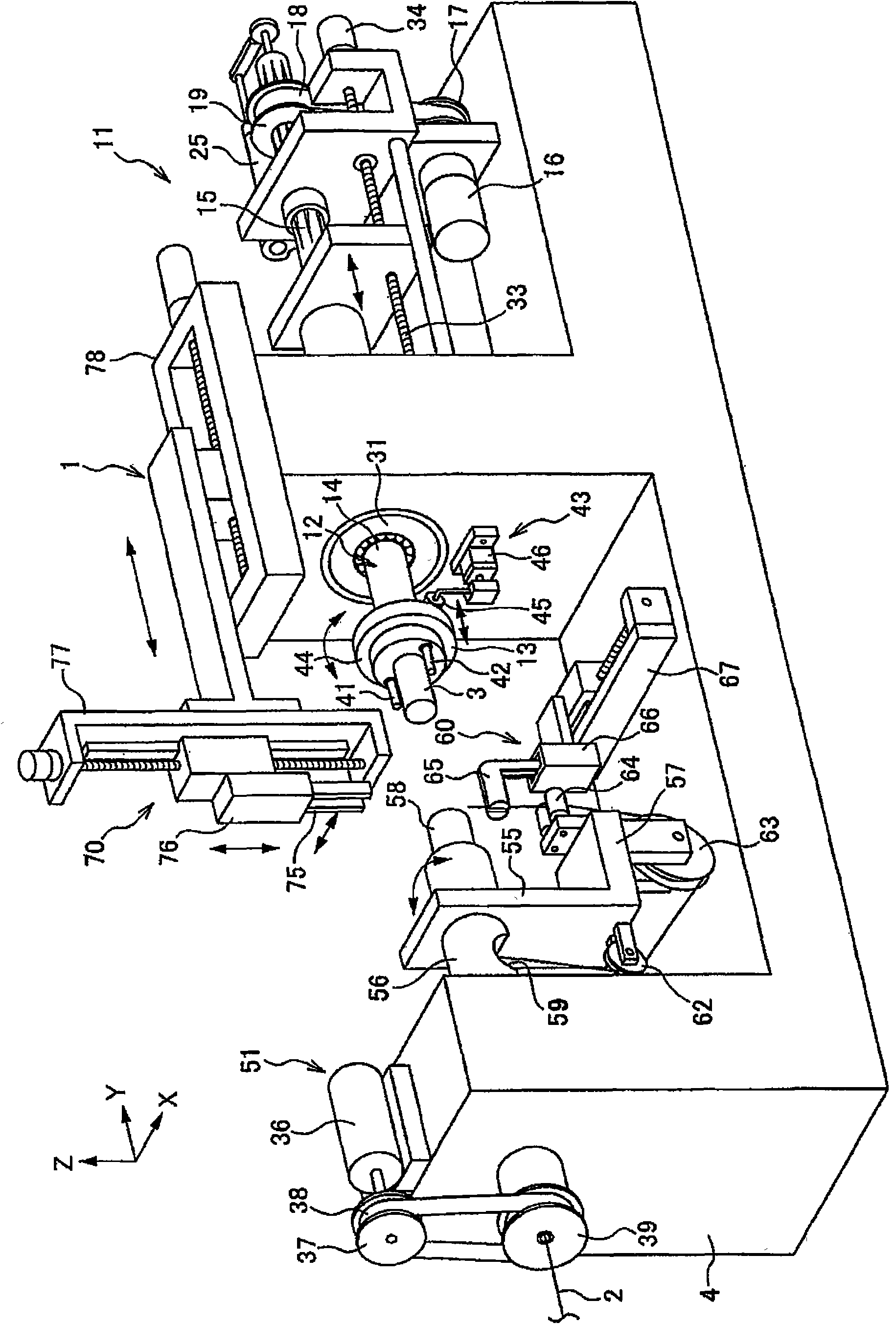
[0025] figure 2 It is a perspective view showing a schematic configuration of a coil winding device (double outer coil winding device) 1 for ...


PUM


Abstract

The present invention provides a method and device for winding coils, capable of setting arbitrarily the position and shape of a down-lead part extending from a coil part, and shaping. In the invention, the following processes are implemented by shaping pins (41, 42) projecting from a coil core flange (13) elastically, namely a winding process of winding wire (2) on a coil core (3) to form the coil part (101) under a condition that the shaping pins (41, 42) are feed into the coil core flange (13); a shaping process of shaping the down-lead parts (102, 103) by making the wire (2) extending from the coil part (101) against the shaping pins (41, 42) and bending under a condition that the shaping pins (41, 42) are projected from the coil core flange (13).

Description

technical field [0001] The present invention relates to a coil winding method and a coil winding device for shaping a lead wire portion extending from a coil portion. Background technique [0002] In a normal coil, the lead wire portion at the winding start end extends from the inner periphery of the spiral coil portion, and the lead wire portion at the winding end extends from the outer periphery of the spiral coil portion. [0003] On the other hand, in the double outer winding coil (also called an α-winding coil), the lead wire portion at the winding start end and the lead wire portion at the winding end end both extend from the outer periphery of the spiral coil portion. [0004] Conventionally, there is a device disclosed in Patent Document 1 as a coil winding device for forming such a double outer coil. [0005] [Patent Document 1] JP Unexamined Publication No. 2001-267171 [0006] However, in such a conventional coil winding device, since the lead wire extending fro...

Claims


Application Information

Patent Timeline
Patent Type & Authority Applications(China)
IPC IPC(8): H01F41/06H01F41/04
Inventor 落合洋平
Owner NITTOKU ENG CO LTD
Why Eureka
Try Eureka