Unlock instant, AI-driven research and patent intelligence for your innovation.
Ion generating element, ion generator, and electric device
What is Al technical title?
Al technical title is built by PatSnap Al team. It summarizes the technical point description of the patent document.
An ion generation and component technology, applied in electrical components, household refrigeration devices, corona discharge devices, etc., can solve the problem of no description, and achieve the effect of improving reliability and suppressing neutralization
Active Publication Date: 2010-01-06
SHARP KK
View PDF5 Cites 5 Cited by
Summary
Abstract
Description
Claims
Application Information
AI Technical Summary
This helps you quickly interpret patents by identifying the three key elements:
Problems solved by technology
Method used
Benefits of technology
Problems solved by technology
As a high-voltage power supply, it is described that a diode is arranged at both ends of the electrodes, and a negative potential power supply or a positive potential power supply is selected by its direction, but there is no description about its switching function.
Method used
Image
Click on the blue label to locate the original text in one second.
Reading with bidirectional positioning of images and text.
Examples
Embodiment Construction
[0057] The ion generating device of the present invention eliminates and effectively releases the generated bipolar ions into the space in order to suppress the neutralization of positive ions and negative ions generated near the electrodes of the ion generating element, instead of using a single ion generating element with Instead of alternately generating positive ions and negative ions in a predetermined period, a plurality of ion generating elements are used to individually generate positive ions and negative ions and release each independently into the chamber (hereinafter referred to as the independent ion releasing method).
[0058] Before adopting the above-mentioned independent ion emission method, the following basic experiments were carried out first. In addition, as the form of the ion generating element used in this experiment, although the structure of needle-shaped electrodes can be adopted, here, it is conceivable to use a discharge electrode provided on the sur...
PUM
Abstract
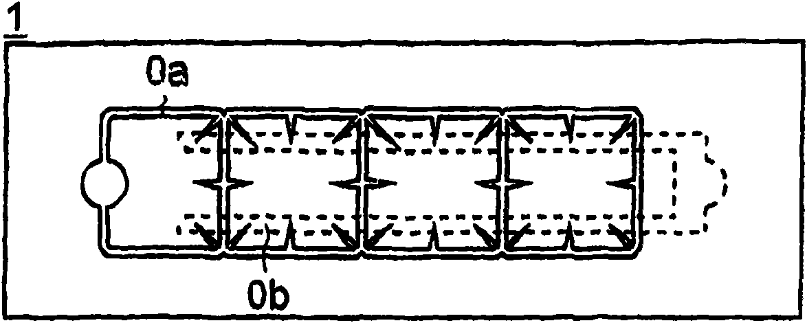
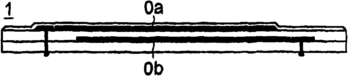
An ion generating element (10) has at least one first discharger (12) for generating positive ions and at least one second discharger (13) for generating negative ions, both fitted or printed on a single dielectric member (11). The first and second dischargers (12) and (13) are each composed of a pair of a first or second discharging electrode (12a) or (13a), respectively, formed on the surface of the dielectric member (11) and a first or second induction electrode (12b) or (13b), respectively, buried in the dielectric member (11), and are arranged both on the same flat surface of the dielectric member (11) but separately from and independently of each other. This construction helps to alleviate the neutralization among the generated ions themselves, thus to effectively release both positive and negative ions, and thereby to enhance the ion generation efficiency.
Description
[0001] This application is a divisional application of the following application, invention name: ion generating element, ion generating device, electrical equipment; application date: May 10, 2004; application number: 200480013304.6 technical field [0002] The present invention relates to an ion generating element capable of decomposing bacteria, fungi, harmful substances, etc. floating in the air by emitting positive ions and negative ions in space, an ion generating device, and electrical equipment equipped with the device. In addition, as an example corresponding to the above-mentioned electrical equipment, it is mainly possible to enumerate electrical equipment installed in enclosed spaces (inside homes, rooms in buildings, hospital wards and operating rooms, inside cars, inside airplanes, inside ships, inside warehouses, and refrigerators). Air conditioners, dehumidifiers, humidifiers, air cleaners, refrigerators, fan heaters, microwave ovens, washing and drying machines...
Claims
Application Information
Patent Timeline
Application Date:The date an application was filed.
Publication Date:The date a patent or application was officially published.
First Publication Date:The earliest publication date of a patent with the same application number.
Issue Date:Publication date of the patent grant document.
PCT Entry Date:The Entry date of PCT National Phase.
Estimated Expiry Date:The statutory expiry date of a patent right according to the Patent Law, and it is the longest term of protection that the patent right can achieve without the termination of the patent right due to other reasons(Term extension factor has been taken into account ).
Invalid Date:Actual expiry date is based on effective date or publication date of legal transaction data of invalid patent.
