Detecting device for output current of voltage regulator and method

An output current detection and voltage regulator technology, applied in output power conversion devices, regulating electrical variables, control/regulation systems, etc., can solve the problems of small voltage changes, noise sensitivity, and easy noise interference.

Inactive Publication Date: 2010-01-06
RICHTEK TECH
View PDF1 Cites 10 Cited by
  • Summary
  • Abstract
  • Description
  • Claims
  • Application Information

AI Technical Summary

Problems solved by technology

[0003] Since the known detection method is to set the detection resistor Rsense on the charging path of the voltage regulator, in order to reduce the output power loss of the detection resistor Rsense, the detection resistor Rsense must be a precision resistor with low resistance, but the low resistance can detect The voltage change is small, and sensitive to noise, susceptible to noise interference
[0004] Therefore, there are above-mentioned inconveniences and problems in the output current detection device of the known voltage regulator.

Method used


Image

  • Detecting device for output current of voltage regulator and method
  • Detecting device for output current of voltage regulator and method
  • Detecting device for output current of voltage regulator and method

Examples


Embodiment Construction

[0095] The present invention will be further described below in conjunction with embodiment and accompanying drawing.

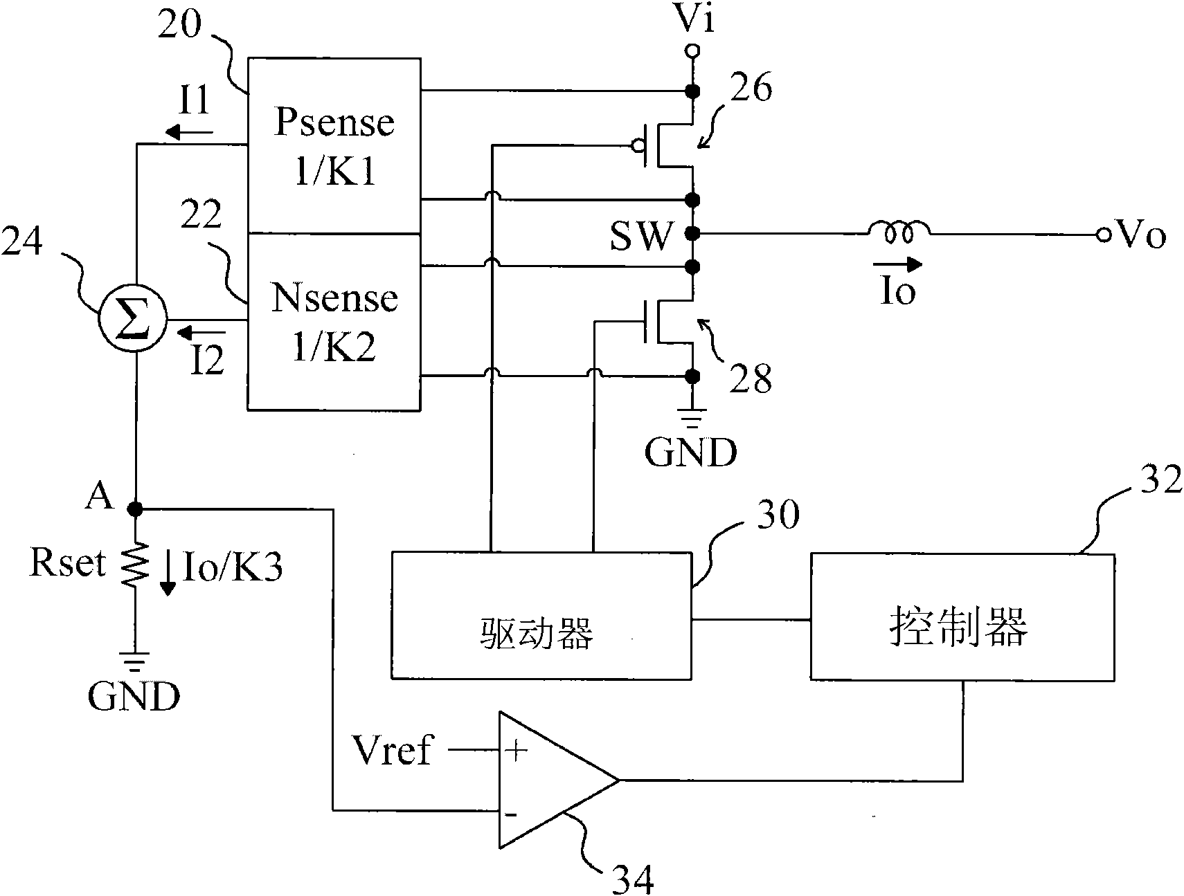
[0096] see now figure 2 , figure 2 is a schematic diagram of the first embodiment of the present invention. As shown in the figure, the upper bridge transistor 26 is connected between the input voltage Vi and the switching node SW, the lower bridge transistor 28 is connected between the switching node SW and the ground potential GND, and the inductor is connected to the switching node SW. The bridge transistor 26 and the lower bridge transistor 28 are switched under the control of the driver 30 to generate an output current Io flowing through the inductor and generate an output voltage Vo at the output terminal. The upper bridge detection circuit 20 senses the current of the upper bridge transistor 26 and generates a current I1 accordingly, and the lower bridge detection circuit 22 senses the current of the lower bridge transistor 28 to generate a current...


PUM


Abstract

The invention discloses a detecting device for output current of a voltage regulator. The voltage regulator comprises an upper bridge assembly, a lower bride assembly and an electrical inductance which are jointly coupled to a switching joint, and the other ends of the upper bridge assembly, the lower bride assembly and the electrical inductance are respectively coupled with an input end, a grounding electric potential and an output end; the voltage regulator also comprises a controller at least controlling the movement of either the upper bridge assembly or the lower bride assembly so as to generate output voltage at the output end. The detecting device for output current comprises an upper bridge current sensing circuit, a lower bridge current sensing circuit and a setting resistance; the detecting device of output current is characterized in that the upper bridge current sensing circuit senses the current of an upper bridge assembly to generate a first current; the lower bridge current sensing circuit senses the current of an lower bridge assembly to generate a second current; a totalling circuit adds the first current and the second current to generate a summation current; thesetting resistance detects the change of the summation current, and resistance change on the setting resistance is provided for the controller to carry out feedback control.

Description

technical field [0001] The invention relates to a voltage regulator, in particular, an output current detection device and method applied to the voltage regulator of a charger. Background technique [0002] It is known that when a voltage regulator is used to provide a regulated current, such as a charger, the common output current detection method is to connect a detection resistor in series with the inductance of the voltage regulator, please refer to figure 1 , figure 1 is a schematic diagram of a known voltage converter. As shown in the figure, the output current Io of the voltage regulator flows through the sense resistor Rsense, such as US Patent No. 6369561, LTC4001 or SMB135, the voltage change on the sense resistor Rsense is related to the output current Io, and the distance between the output current Io The proportional relationship of 1:1 is fixed, and the voltage change on the sense resistor Rsense is differentially input to the controller 12 through the error ...

Claims


Application Information

Patent Timeline
Patent Type & Authority Applications(China)
IPC IPC(8): H02M3/155
Inventor 龚能辉朱冠任
Owner RICHTEK TECH
Why Eureka
Try Eureka