
Electronic device

A technology of electronic equipment and boards, which is applied in the field of electronic equipment, can solve the problems of accumulation, influence, fan noise and vibration, etc., and achieve the effect of increasing heat dissipation efficiency, reducing manufacturing cost, and increasing heat dissipation efficiency

Inactive Publication Date: 2010-01-06
WISTRON CORP
View PDF0 Cites 46 Cited by
  • Summary
  • Abstract
  • Description
  • Claims
  • Application Information

AI Technical Summary

Problems solved by technology

[0004] 1. For increasing the speed of the fan, although the fan speed increases as the system temperature rises to increase the air intake, the number of air intake holes and the air intake area formed by the air intake holes on the housing of the electronic device are fixed. , therefore, it is not possible to effectively increase the air intake, and the fan is prone to noise and vibration under high-speed operation, causing adverse effects on the system
[0005] 2. For a fan with a thin thickness and a large area, the housing of the electronic device needs to be equipped with a large air inlet hole for the fan, which will affect the overall appearance of the electronic device, and dust is easy to accumulate in the air through the air inlet hole. Inside the shell
[0006] 3. For the method of using water cooling system and heat pipe, both of them are currently expensive heat dissipation modes, which will increase the manufacturing cost of electronic equipment
[0007] In addition, in order to improve the heat dissipation efficiency of the current notebook computer, a large-area air intake hole is generally opened on the bottom surface or the side of the notebook computer casing to increase the air intake. Holes enter the interior of the enclosure and accumulate within the enclosure

Method used


Image

  • Electronic device
  • Electronic device
  • Electronic device

Examples


Embodiment Construction

[0066] The aforementioned and other technical contents, features and effects of the present invention will be clearly presented in the following detailed description of twelve preferred embodiments with reference to the accompanying drawings. Through the description of the specific embodiment, when the technical means and effects of the present invention are adopted to achieve the intended purpose, a more in-depth and specific understanding can be obtained. However, the temperature settings mentioned in the drawings and contents are only for reference and description. It is not intended to limit the invention.

[0067] Before the present invention is described in detail, it should be noted that in the following description, similar elements are denoted by the same reference numerals.

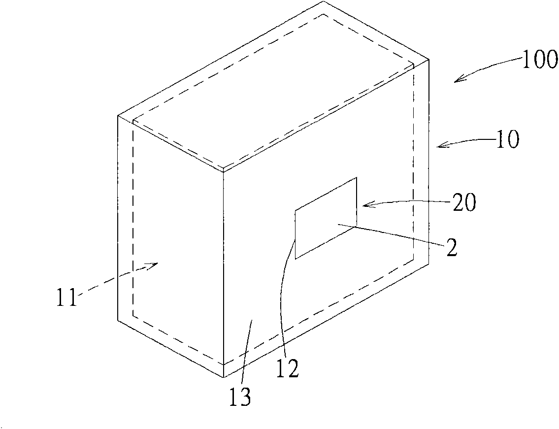
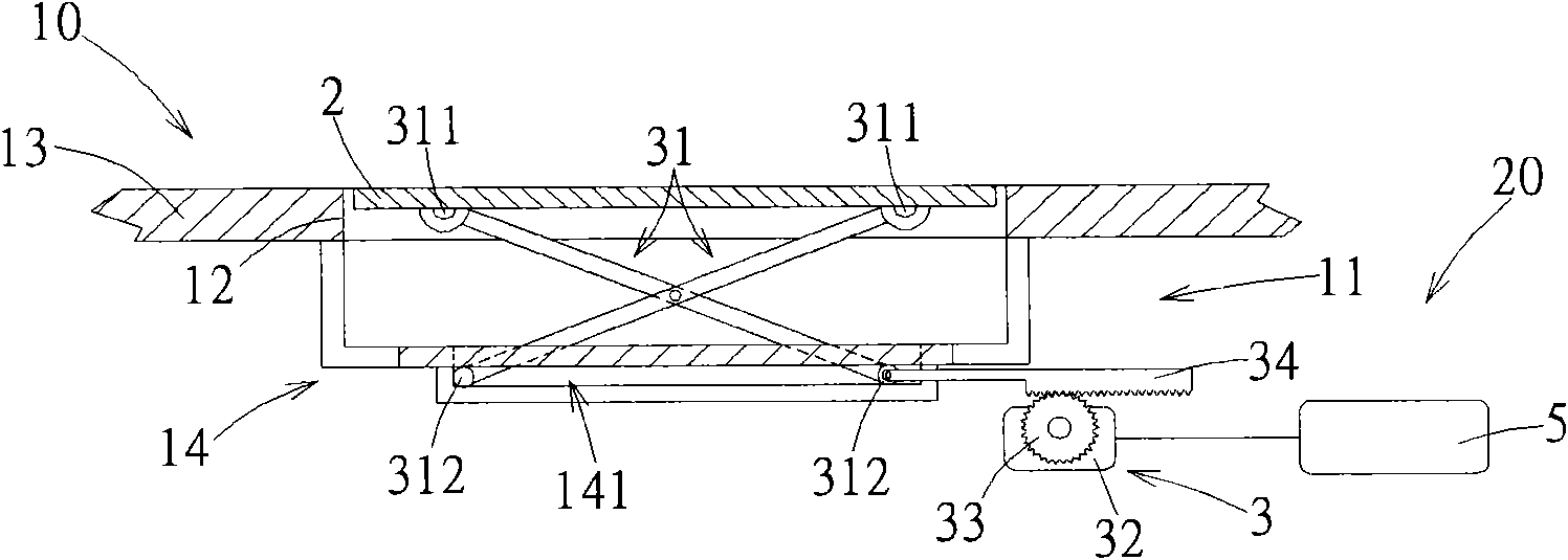
[0068] Such as figure 1 As shown, it is the first preferred embodiment of the electronic equipment of the present invention. The electronic equipment 100 includes a casing 10 and an air volume ...


PUM


Abstract

The invention discloses an electronic device comprising a housing and an air volume adjusting device; wherein, the housing is defined with a holding space and an air inlet causing the holding space to be communicated with the outside; the air volume adjusting device comprises a plate piece for covering the air inlet and an actuating mechanism, wherein, the actuating mechanism can drive the plate piece to move to open the air inlet along with temperature change of the holding space; the supply air rate of the holding space can be increased by the configuration of the air volume adjusting device so as to effectively improve the heat dissipation efficiency of a heat dissipation fan and lower the possibility of system halt due to poor heat dissipation in the system; in addition, the air volume adjusting device with simple structure can effectively increase heat dissipation efficiency and does not need to adopt complex heat dissipation assemblies with high price and complex structure, so that manufacturing cost can be effectively lowered.

Description

technical field [0001] The invention relates to an electronic device, in particular to an air volume regulating device for the electronic device. Background technique [0002] As the functions of electronic equipment such as desktop computers or servers are becoming more and more powerful, and the volume tends to be thinner and lighter in design, the volume of heat dissipation components will also be reduced under the limited space constraints, which will affect the efficiency of heat dissipation, resulting in The system crashes due to poor heat dissipation. Therefore, there are various heat dissipation methods currently on the market to solve the above-mentioned problems, such as increasing the fan speed of the heat dissipation component, using a fan with a thin thickness and a large area, or using a water cooling system and a heat pipe. [0003] However, the aforementioned heat dissipation methods still have the following disadvantages: [0004] 1. For increasing the spe...

Claims


Application Information

Patent Timeline
IPC IPC(8): H05K7/20G06F1/20G05D27/02G05D7/03G05D23/20
Inventor 武文钦张奇嵩谢松佑陈明智
Owner WISTRON CORP
Learn More