Dish-shaped parts rotary end surface supporting roller differential mechanism

A technology of disc parts and differential mechanisms, applied in the direction of support, metal processing machinery parts, clamping, etc., can solve the problems of large driving torque, surface wear of drag rollers, poor motion stability, etc., to reduce surface wear and reduce Sliding friction and the effect of reducing the difference in linear speed

Inactive Publication Date: 2011-06-08
天津天丰中高频感应淬火设备有限公司
View PDF0 Cites 0 Cited by
  • Summary
  • Abstract
  • Description
  • Claims
  • Application Information

AI Technical Summary

Problems solved by technology

[0004] The purpose of the present invention is to solve the technical defects of serious wear on the surface of the drag roller, poor motion stability and large driving torque

Method used


Image

  • Dish-shaped parts rotary end surface supporting roller differential mechanism
  • Dish-shaped parts rotary end surface supporting roller differential mechanism
  • Dish-shaped parts rotary end surface supporting roller differential mechanism

Examples


Embodiment Construction

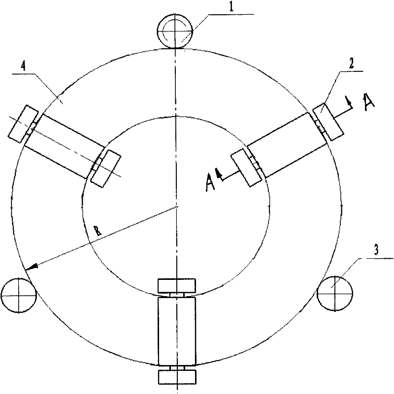
[0014] The invention is in figure 1 It is realized by replacing the dragging roller mechanism in the existing disc-type parts rotating end support mechanism shown. The specific implementation is as follows:

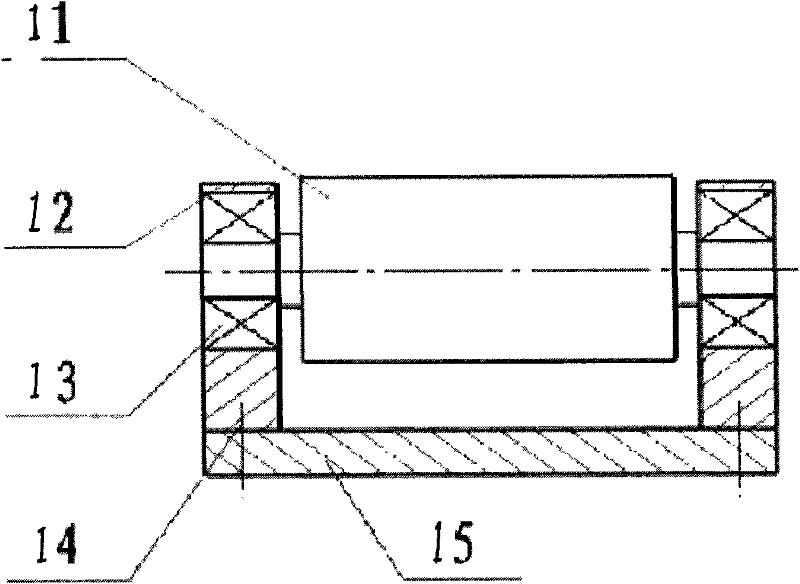
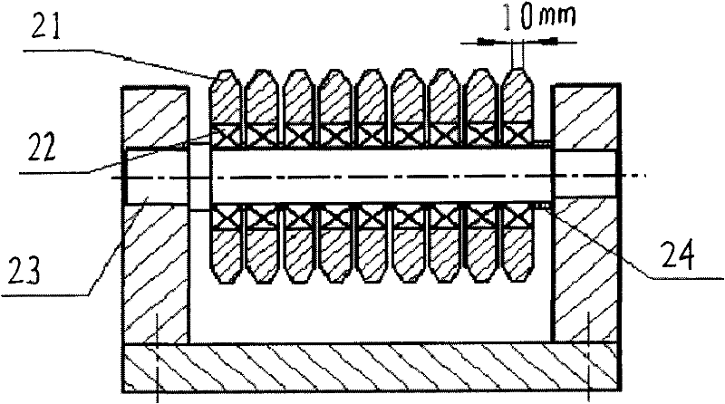
[0015] The rotating end support mechanism of disk parts includes: the main driving wheel for driving the rotation of the disk parts, which drives the rotation of the disk parts through the friction with the outer peripheral surface of the disk parts; Function; the drag roller mechanism is located under the end face of the disc parts and plays a supporting role. The number of the drag roller mechanisms is 3 and is evenly distributed; the drag roller mechanism includes: a bottom plate, a bracket fixedly connected to the bottom plate, and a fixed bracket in the middle of the bracket. The shaft and the fixed shaft are fixedly connected with the support; the rolling bearings arranged side by side on the fixed bearings, the number of rolling bearings is 9; the spacers are resp...


PUM


Abstract

The invention relates to a machine accessory equipment, further relates to a dish-shaped parts rotary end surface supporting roller differential mechanism, aiming at solving the technical defect of the serious abrasion of the roller surface. The dish-shaped part rotary end surface supporting roller differential mechanism arranged below the dish-shaped part end surface plays a supporting role, andthe number of the differential mechanisms is at least three. The roller mechanism comprises a base plate, a bracket fixedly connected with the base plate and a fixed shaft put up in the middle of thebracket, and the fixed shaft is fixedly connected with the bracket. Rolling bearings are mounted on a fixed bearing side by side, and the number thereof is at least two. Spacer bushes are arranged between the two end surfaces of the rolling bearing and the bracket. Compared with the prior art, the invention has the advantages of greatly reducing the linear speed difference of the workpiece and the roller surface and lowering the sliding friction of the roller and the workpiece surface, thus reducing the surface abrasion of the roller, due to the design of the dish-shaped parts rotary end surface supporting roller differential mechanism.

Description

technical field [0001] The invention relates to a machine tool auxiliary equipment, and further relates to a drag roller differential mechanism supported by a rotating end surface of a disk part. Background technique [0002] as attached figure 1 As shown, in the prior art, when a large disc-like part rotates horizontally, since the drag roller on the lower end surface is an integral cylindrical roller, the linear speed of the outer surface of the drag roller is different during the rotation process, and the outer circular surface is in contact with the workpiece The surface produces relative sliding motion, which makes the surface of the drag roller wear seriously, the motion stability is poor, and the driving torque is large. [0003] The linear velocity of each point on the end face of the workpiece is 2πRn (n=speed, R=radius of the workpiece), that is, the speed of each point is proportional to R, as shown in the attached figure 2 As shown, the radius difference betwe...

Claims


Application Information

Patent Timeline
Patent Type & Authority Patents(China)
IPC IPC(8): B23Q3/00
Inventor 常玉昆李惠玲
Owner 天津天丰中高频感应淬火设备有限公司
Why Eureka
Try Eureka