
All-Terrain Vehicle and Method of Increasing Passability Thereof

a technology of all-terrain vehicles and passability, applied in the field of all-terrain vehicles and the increase of passability of such vehicles, can solve the problems of complex structure and manufacture technology, high price and maintenance costs, and insufficient life time of the main assembly

Inactive Publication Date: 2011-07-28
IVANKOV MIKHAIL V +1
View PDF3 Cites 4 Cited by
  • Summary
  • Abstract
  • Description
  • Claims
  • Application Information

AI Technical Summary

Benefits of technology

[0010]The present invention is directed at overcoming the indicated disadvantages of the known technical solutions and ensures the achievement of the technical result in the form of simplifying the all-terrain vehicle transmission, increasing the reliability, and decreasing the wheels surface wear, specifically for wheels having a non-hub drive.
[0011]For this purpose, the first object of the present invention provides a method for increasing the cross-country ability of all-terrain vehicle comprising at least an engine transmission section and a pair of caterpillar drives from each of the side faces of the engine transmission section, the method including steps of: mounting the engine transmission section on a support frame provided with at least two rotatably mounted axles; fixing at least two wheels on each of those axles so as the distance between the maximal radius circles of those wheels at each of those axles corresponding approximately the distance between the midline of the caterpillar drives; fixing the engine transmission section on the support frame so as a contact pattern of each of the caterpillar drives with a surface of the corresponding wheel being not less than a contact pattern of the lower portion of this wheel with the movement supporting surface.
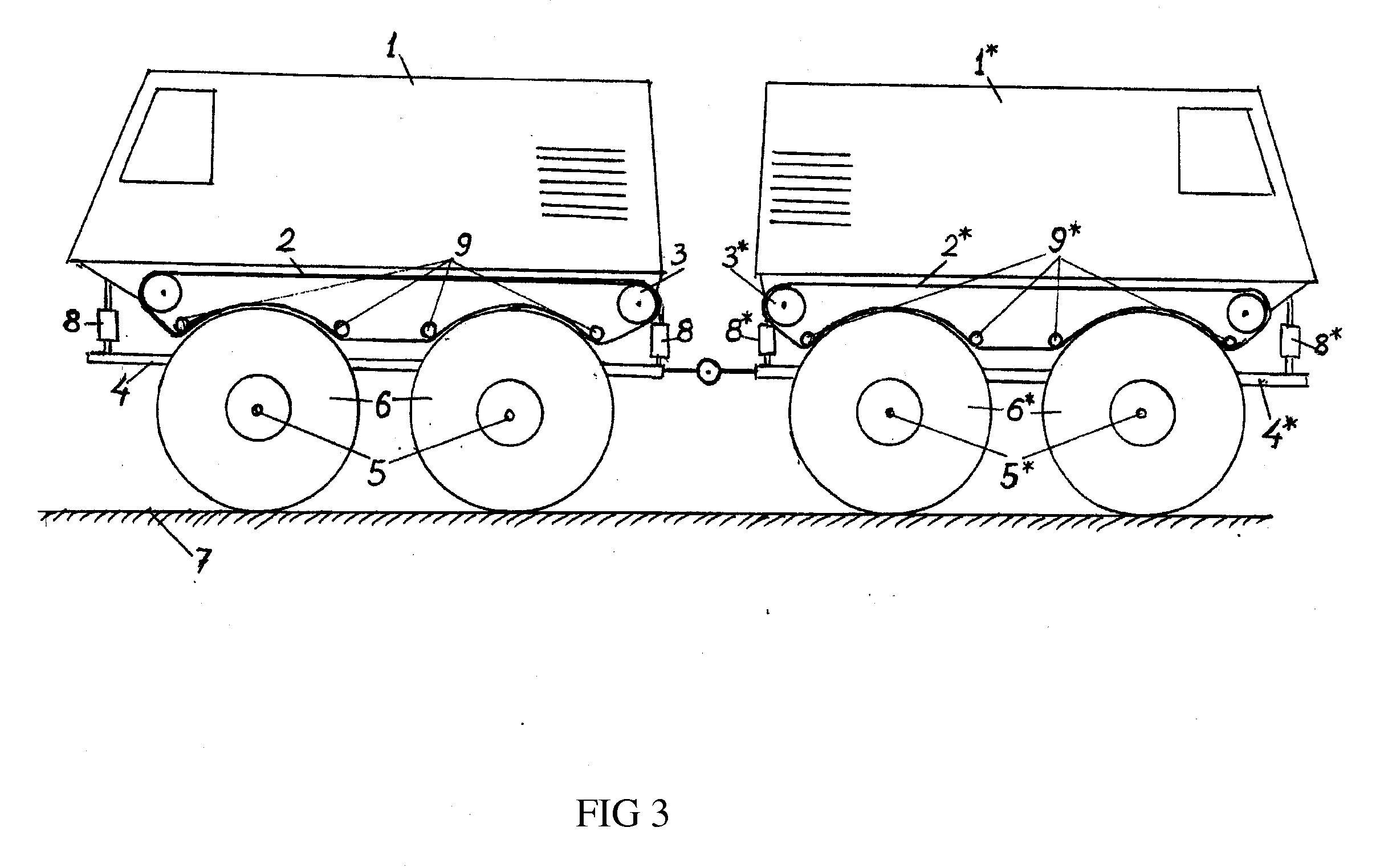
[0014]One more additional feature of the method according to the present invention is in that two all-terrain vehicles are joined by means of the transmission from the engine transmission section of the first all-terrain vehicle to the transmission section of the second all-terrain vehicle, the joint being configured for allowing the second all-terrain vehicle to deviate from the movement direction of the first all-terrain vehicle for ensuring a turn of the joined all-terrain vehicles.
[0018]One more additional feature of this all-terrain vehicle is in comprising further a same second all-terrain vehicle joined with the first all-terrain vehicle by means of the transmission from the engine transmission section of the first all-terrain vehicle to the transmission section of the second all-terrain vehicle, the joint being configured for allowing the second all-terrain vehicle to deviate from the movement direction of the first all-terrain vehicle for ensuring a turn of the joined all-terrain vehicles.

Problems solved by technology

The disadvantage of those technical solutions consists in complexity of their structure and manufacture technology, a great price and maintenance costs, insufficient life time of the main assemblies, and low reliability indices.
The disadvantage of those technical solutions consists in that, in order for driving the pneumatic wheels having a great diameter, as well as for ensuring the required transmission reliability indices, complex and massive assemblies of the transmission are employed, such as portal tractor reduction axles, torque dividers, onboard reducing gears, overload controlled and uncontrolled clutches, etc., which increases the total weight of the vehicle, lowers the transmission performance factor, increases the fuel consumption, and decreases the reliability indices.
The disadvantage of this technical solution consists in a low reliability due to the fact that the track is pressed to the roller in a small area whereupon a great pressure force is necessary resulting in a rapid wear.

Method used


Image

  • All-Terrain Vehicle and Method of Increasing Passability Thereof
  • All-Terrain Vehicle and Method of Increasing Passability Thereof
  • All-Terrain Vehicle and Method of Increasing Passability Thereof

Examples


Embodiment Construction

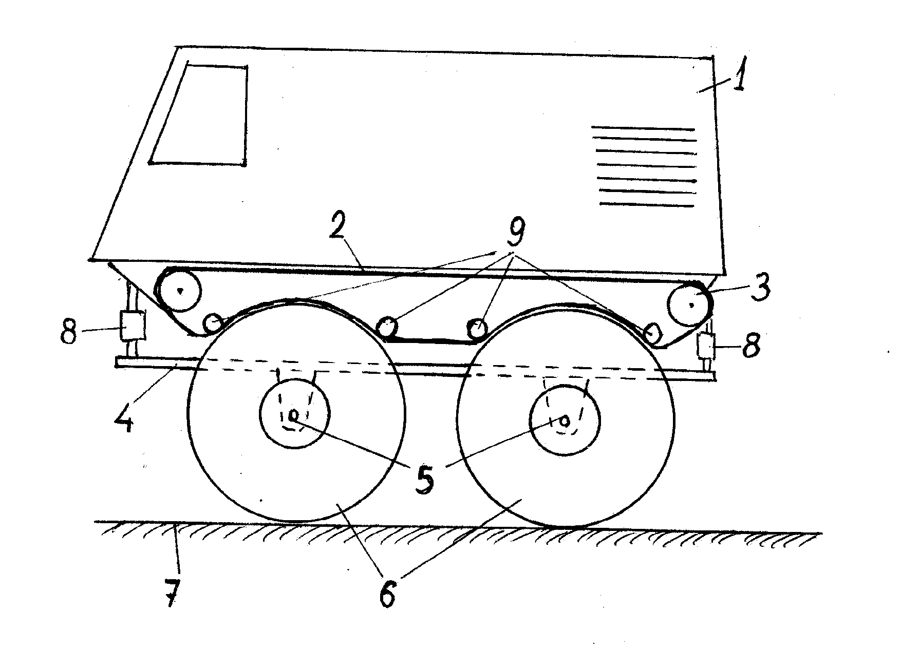
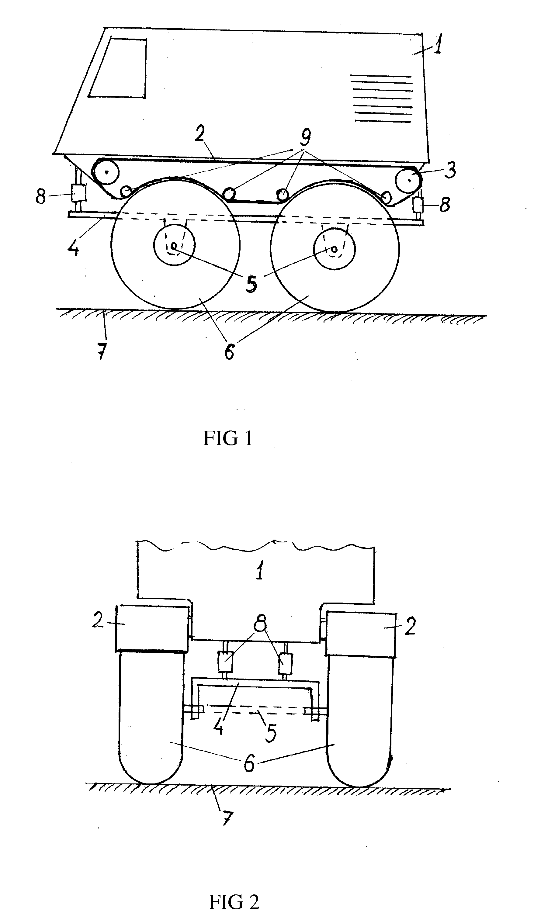
[0023]As shown in FIG. 1, the all-terrain vehicle of the present invention comprises an engine transmission section 1 which is an independent vehicle, for example, a tracked cross-country vehicle or a car. Alternatively, the engine transmission section 1 could be designed especially for the all-terrain vehicle of the present invention. It is essential that the engine transmission section 1 has, as is clear from its name, an engine (motor) of any type, for example, a combustion engine, a diesel engine, an electrical engine, etc., and a transmission to at least one of its axles for transmitting a rotation from the engine. At the drawing, the rear axle is depicted as an example of such one axle, but this is not necessarily so, and the driving axle can be, for example, the front axle, or both axles, the front and rear, can be the drive ones. In the presence of more than two axles in the engine transmission section 1, any or all of those axles could be the drive ones. It is clear that th...


PUM

PropertyMeasurementUnit
Diameteraaaaaaaaaa
Volumeaaaaaaaaaa
Volumeaaaaaaaaaa

Abstract

The invention relates to the automotive technique. Its use while creating new and improving current all-terrain vehicles allows to ensure the achievement of the technical result in the form of simplifying the all-terrain vehicle transmission, increasing the reliability, and decreasing the wheels surface wear, specifically for wheels having a non-hub drive. For this purpose, an all-terrain vehicle comprises: an engine transmission section; a pair of caterpillar drives from each of the side faces of the engine transmission section; a support frame provided with at least two rotatably mounted axles, on each of which at least two wheels are fixed so as the distance between the maximal radius circles of those wheels at each of those axles corresponding approximately the distance between the midline of the caterpillar drives; wherein the engine transmission section being fixed on the support frame so as a contact pattern of each of the caterpillar drives with a surface of the corresponding wheel being not less than a contact pattern of the lower portion of this wheel with the movement supporting surface.

Description

RELATED APPLICATIONS[0001]This application claims priority to Russian application RU 2009139842 filed on Oct. 29, 2009, which is incorporated herein by reference in its entirety.FIELD OF THE INVENTION[0002]This invention relates to the automotive technique, and more particularly, to the method for increasing the cross-country ability all-terrain vehicle and to corresponding all-terrain vehicle.BACKGROUND OF THE INVENTION[0003]At present, various methods for increasing the cross-country ability of all-terrain vehicles are known.[0004]Known is the method for increasing the cross-country ability, pursuant to which method an all-terrain vehicle is provided with tracks in the form of pneumatic cushion (RU 2119438 C1, publ. on Sep. 27, 1998). Another technical solution consists in arranging the engine transmission compartment within a pneumatic envelope (RU 2284941 C1, publ. on Oct. 10, 2006).[0005]The disadvantage of those technical solutions consists in complexity of their structure and...

Claims


Application Information

Patent Timeline
IPC IPC(8): B62D53/00B60K8/00B23P17/00
CPCB60K17/043Y10T29/49826B62D49/0621B60K17/342
Inventor IVANKOV, MIKHAIL V.IVANKOV, MAKSIM M.
Owner IVANKOV MIKHAIL V
Learn More