Dry-hanging structure of stone curtain wall

A stone curtain wall and dry-hanging technology, which is applied in the direction of walls, building components, building structures, etc., can solve the problems of three-dimensional adjustment of the plate, high cost and installation cost, etc., and achieve the effect of simple structure, accurate and convenient installation, and convenient installation

Inactive Publication Date: 2010-01-13
FANGYUAN CONSTR GRP REAL ESTATE DEVT CO LTD
View PDF0 Cites 48 Cited by
  • Summary
  • Abstract
  • Description
  • Claims
  • Application Information

AI Technical Summary

Problems solved by technology

Traditional curtain wall dry hanging methods include butterfly type, T type, back bolt type, etc. Although they are widely used in existing production, there are certain problems in the process of use. Among them, the butterfly type and T type structures cannot make the plates four Three-dimensional adjustment of each corner is realized, and at the same time, when replacing a panel, all stone panels that need to be removed for interference can be replaced in order to replace the panels that need to be replaced, and must be installed in order; the curtain wall of the back-bolt structure needs to use two beams to achieve The installation of one plate, the cost and installation cost are high

Method used


Image

  • Dry-hanging structure of stone curtain wall
  • Dry-hanging structure of stone curtain wall
  • Dry-hanging structure of stone curtain wall

Examples


Embodiment 1

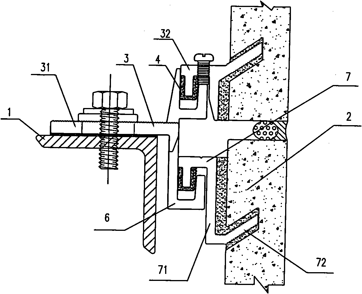
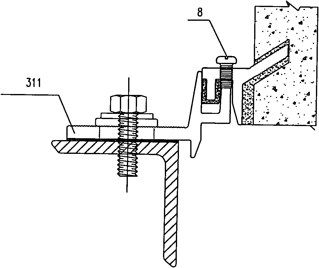
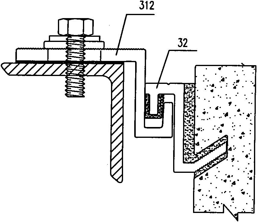
[0029] Such as Figure 1 to Figure 4 As shown, a dry-hanging structure of a stone curtain wall of the present invention comprises a beam 1, a stone plate 2 and a dry-hanging part 3 fixed between the beam 1 and the stone plate 2, and the dry-hanging part 3 consists of a hanging seat fixed on the crossbeam 1 31 and the pendant 32 fixed on the stone plate 2 are connected. The hanger 31 is composed of a split upper hanger 311 and a lower hanger 312. The two hangers are fixed side by side on the same beam, and the lower hanger 312 is located on the upper hanger 311. The outside of the upper hanging seat 311 and the side of the lower hanging seat 312 extend outward to form a hook 6 with a groove in the upward direction of the hook mouth. There is a flexible material 4, and the hanging seat 31 is provided with an elongated bolt hole 5 for adjusting the front and rear deviation of the stone plate. In the embedded groove of hanger hook 6 and hook and cooperate with it. In this embodi...

Embodiment 2

[0031] Such as Figure 5 , Figure 6 and Figure 7 As shown, the difference between this embodiment and the above-mentioned embodiment is that the supporting part connected to the hanging part 7 is a flat plate 9 with a bolt hole on it, and the bolt passes through the hole to fix the hanging part and the stone plate. .

Embodiment 3

[0033] Such as Figure 8 , Figure 9 and Figure 10 As shown, the difference between this embodiment and the above-mentioned two embodiments is that the pendant 32 includes two sets of connection fittings composed of hooks 10 and grooves 11 respectively. The opening of the groove of the connecting fitting is upward, and is connected with the lower end of the stone plate body; the groove opening of the connection fitting located below is downward, and the groove is connected with the upper end of another stone plate body.


PUM


Abstract

The invention discloses a dry-hanging structure of a stone curtain wall, which comprises a curtain wall frame, a beam, a stone plate and a dry-hanging element fixed between the beam and the stone plate, wherein the dry-hanging element is formed by connecting a hanging seat fixed on the beam and a hanging element fixed on the stone plate; a lateral part of the hanging seat extends outwards to form a hook with an upward hook mouth; and the end part of the hanging element on the stone plate is in hooking fit with the hook. The dry-hanging structure of the stone curtain wall is characterized in that: a joint between the hanging element and the hanging seat is provided with a bolt which is used for adjusting the height deviation of the plate; the hanging seat is provided with a long hole which is used for adjusting length deviation; and the inside of the long hole is provided with a fixing element for fixedly connecting the hanging seat and the beam. The stone plate in the dry-hanging structure of the stone curtain wall can be separately replaced, the installation is convenient and secure, and the cost and the installation charge are saved, thus the dry-hanging structure of the stone curtain wall has good promotion value.

Description

technical field [0001] The invention relates to the technical field of building curtain walls, and more specifically relates to a stone curtain wall installation and fixing structure. Background technique [0002] At present, the common stone curtain wall dry hangings on the market are generally connected and fixed by setting up columns, beams and dry hangings between the stone slab and the wall. There are many types of dry hangings on the market, and each dry hanging has a corresponding The installation method, and the dry hanging method is directly related to the structure, installation and cost of the curtain wall. Traditional curtain wall dry hanging methods include butterfly type, T type, back bolt type, etc. Although they are widely used in existing production, there are certain problems in the process of use. Among them, the butterfly type and T type structures cannot make the plates four Three-dimensional adjustment of each corner is realized, and at the same time, ...

Claims


Application Information

Patent Timeline
Patent Type & Authority Applications(China)
IPC IPC(8): E04B2/88E04F13/22
Inventor 杜军桦
Owner FANGYUAN CONSTR GRP REAL ESTATE DEVT CO LTD
Why Eureka
Try Eureka