
Low-temperature gas liquefaction and separation system applying effect of segregation

A technology for liquefaction separation and segregation separation, which is applied in the field of low-temperature gas liquefaction separation systems and can solve problems such as complex structures

Active Publication Date: 2010-01-13
TECHNICAL INST OF PHYSICS & CHEMISTRY - CHINESE ACAD OF SCI
View PDF10 Cites 5 Cited by
  • Summary
  • Abstract
  • Description
  • Claims
  • Application Information

AI Technical Summary

Problems solved by technology

[0008] Aiming at the problems of complex structure in the commonly used low-temperature liquefaction separation process, the patent of the present invention proposes a gas liquefaction separation system using the effect of segregation condensation separation, which has the advantages of simple equipment, safe and reliable operation, low energy consumption, and does not include a stripping tower / Distillation tower and other large and complex equipment, and the separation effect can meet the requirements and low cost.

Method used


Image

  • Low-temperature gas liquefaction and separation system applying effect of segregation
  • Low-temperature gas liquefaction and separation system applying effect of segregation
  • Low-temperature gas liquefaction and separation system applying effect of segregation

Examples


Embodiment 1

[0045] Embodiment 1: prepare the gas cryogenic liquefaction separation system of a 1-stage separation, for containing ethylene (C 2 h 4 ) and C 3+ Ethylene gas and C in the chemical tail gas of hydrocarbons 3+ Recovery of hydrocarbons.

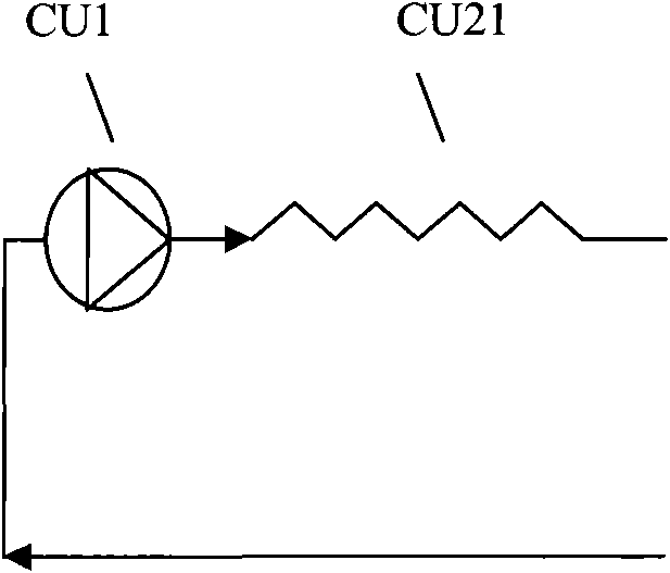
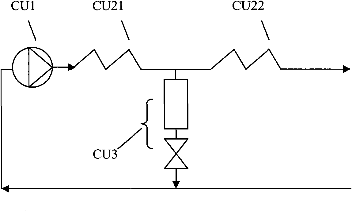
[0046] The general connection method of the separation system can be found in figure 1, The compressor module CU adopts Figure 1.1 The structure shown; the cooling segregation and separation module can adopt the first cooling segregation sub-module S1, the second cooling segregation sub-module S2, the third cooling segregation sub-module S3 or the fourth cooling segregation sub-module S4 , the present embodiment adopts the fourth cooling sub-condensation sub-module S4 (see Figure 2.4 ); the liquefaction separation module TU adopts Figure 3.5 The structure shown; the connection mode of the refrigeration system is: the high-pressure outlet of the compressor module CU is connected to the high-pressure refrigerant inlet of the fourth coo...

Embodiment 2

[0048] Embodiment 2: prepare the gas cryogenic liquefaction separation system of a 1-level separation, for containing ethylene (C 2 h 4 ) and C 3+ Ethylene gas and C in the chemical tail gas of hydrocarbons 3+ Recovery of hydrocarbons. The general connection method of the separation system can be found in figure 1, Wherein the compressor module and the cooling segregation and separation module are the same as those in Embodiment 1, and the liquefaction separation module TU adopts Figure 3.6 The structure shown, the connection mode of the refrigeration system and the separated gas pipeline are the same as those in Embodiment 1.

[0049] In the cooling and condensing separation module of the system, the components containing three or more carbon atoms in the chemical tail gas are cooled at a low temperature and discharged as liquids, and the unliquefied gas enters the liquefaction separation module TU; in TU, ethylene is liquefied and separated, After the unliquefied tail...

Embodiment 3

[0050] Example 3: A gas low-temperature liquefaction separation system with two stages of separation is prepared for the liquefaction of coalbed methane. The general connection method of the system can be found in figure 1, Wherein the compressor module is the same as in embodiment 1, and the liquefaction separation module TU adopts Figure 3.1 structure shown. The cooling segregation and separation module SU is composed of 2-stage cooling segregation and separation sub-modules SU1 and SU2. The third cooling sub-condensation sub-module S3, the fourth cooling sub-condensation sub-module S4 or any combination thereof. In this example, the sub-module SU1 for cooling and decondensation adopts the second sub-module for cooling and decondensation S2 (see Figure 2.2 ); the sub-module SU2 for cooling and segregation adopts the third sub-module for cooling and condensing S3 (see Figure 2.3 ). The connection mode of the refrigeration system is: the high-pressure outlet of the comp...


PUM


Abstract

The invention relates to a low-temperature gas liquefaction and separation system applying the effect of segregation, which comprises a compressor module, a cooling and segregation module and a liquefaction and separation module, wherein a high-pressure outlet of the compressor module is connected with a refrigerant high-pressure inlet of the cooling and segregation module; a refrigerant high-pressure outlet of the cooling and segregation module is connected with a refrigerant high-pressure inlet of the liquefaction and separation module; a refrigerant low-pressure outlet of the liquefaction and separation module is connected with a refrigerant low-pressure inlet of the liquefaction and separation module, and a refrigerant low-pressure outlet of the cooling and segregation module is connected with a lower-pressure inlet of the compressor module; after pretreatment, mixed gas required to be separated enters the cooling and segregation module from a separated gas inlet and then enters the liquefaction and separation module; liquid separated out by each stage and tail gas output by an end stage enters respective preceding stages as required, and cold energy is recovered stage by stage or directly output. The system is driven by a single compressor so as to have reliable and simple operation, applies the segregation to realize separation in a heat exchanger and has simple structure and flexible arrangement.

Description

technical field [0001] The invention relates to a gas low-temperature liquefaction separation system, in particular to a gas low-temperature liquefaction separation system using the segregation condensation separation effect. Background technique [0002] Natural gas, coke oven gas, coal bed methane and some chemical tail gases are very important energy and resources. If these gases can be fully developed and utilized, it will be of great significance for alleviating the increasingly tense energy and environmental pressure and improving the utilization efficiency of resources. Usually these gases have complex components and are multi-component mixtures. In order to make rational use of these gases and facilitate storage and transportation, liquefaction and separation have become an important technical means, especially for gas sources that are not suitable for pipeline transportation , such as remote and discrete gas sources. [0003] Generally, the main components of the a...

Claims


Application Information

Patent Timeline
Patent Type & Authority Applications(China)
IPC IPC(8): F25J3/00
Inventor 吴剑峰公茂琼董学强
Owner TECHNICAL INST OF PHYSICS & CHEMISTRY - CHINESE ACAD OF SCI
Learn More