Circuit breaker

A circuit breaker and circuit technology, applied to circuits, circuit breaker parts, electric switches, etc., can solve the problems of reduced driving force and increased flow path impedance, so as to reduce the driving force, suppress the improvement of current limiting performance, and reduce the burden Effect

Inactive Publication Date: 2012-05-23
MITSUBISHI ELECTRIC CORP
View PDF5 Cites 0 Cited by
  • Summary
  • Abstract
  • Description
  • Claims
  • Application Information

AI Technical Summary

Problems solved by technology

However, due to the structure in which the flow path resistance between the arc extinguishing plate and the arc moving conductor increases, as a result, the driving force generated by the air flow toward the external exhaust port, which makes the arc move at a high speed, is reduced. Necessary to move to arc extinguishing plate

Method used


Image

  • Circuit breaker
  • Circuit breaker
  • Circuit breaker

Examples


Embodiment approach 1

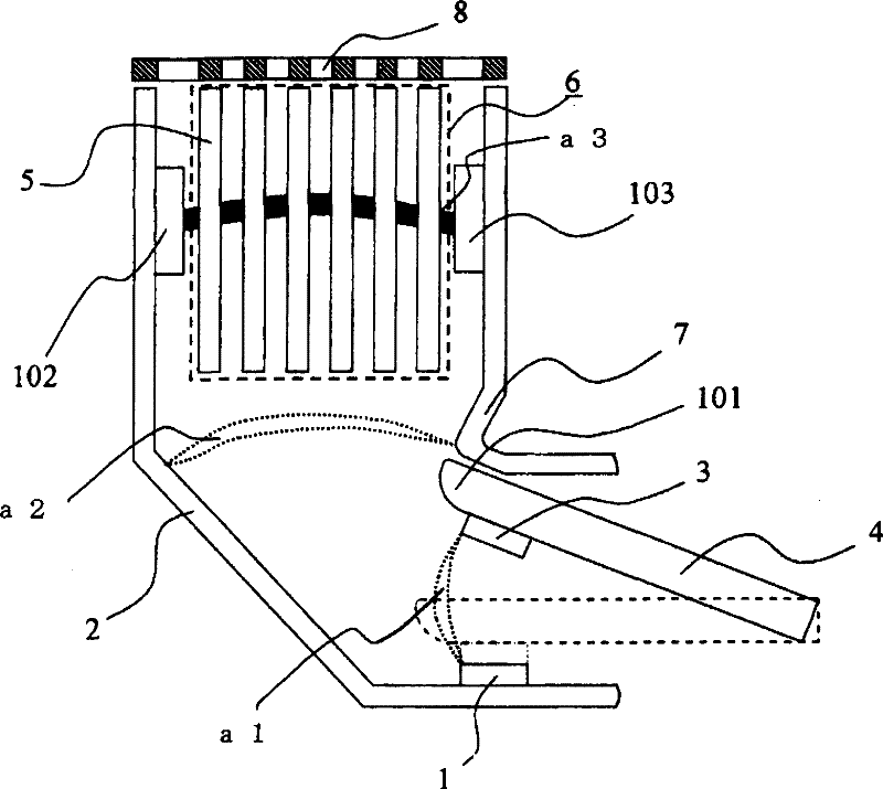
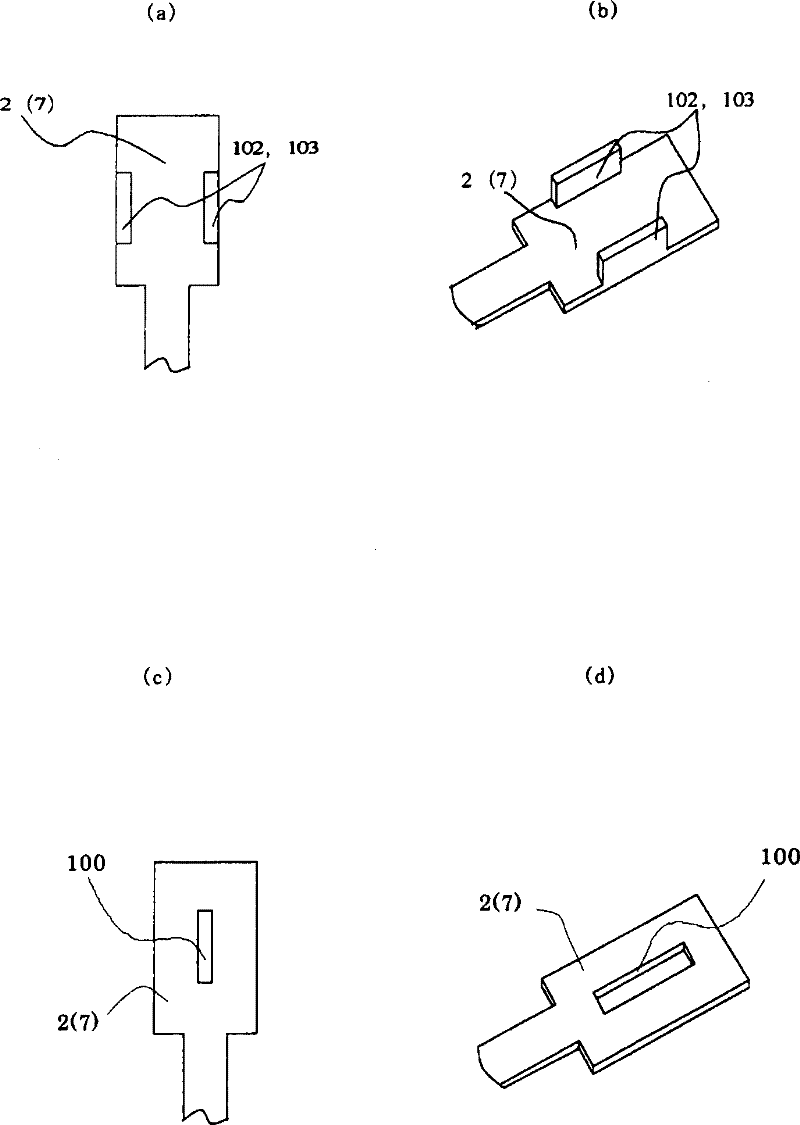
[0009] Embodiment 1 Figure 1~2 It is a drawing for explaining the arc-extinguishing chamber of the circuit interrupter of Embodiment 1, More specifically, figure 1 is the side view of the arc chamber, figure 2 (a) is a front view thereof, and (b) is a perspective view thereof. Although not shown in these figures, this arc extinguishing chamber integrally accommodates a relay unit that detects an abnormal current and issues an opening command, and a drive mechanism unit that transmits the same command, etc., in a container made of an insulator. . in addition, figure 2 (c) and (d) represent modifications of Embodiment 1, and are described in paragraph 0014 of this specification.

[0010] Such as figure 1 As shown, the arc suppression chamber is composed of the following parts: a fixed contact side arc moving conductor 2 with a fixed contact 1; a movable contact 4, which has a movable contact 3 that is in contact with or separated from the fixed contact 1, And it forms a...

Embodiment approach 2

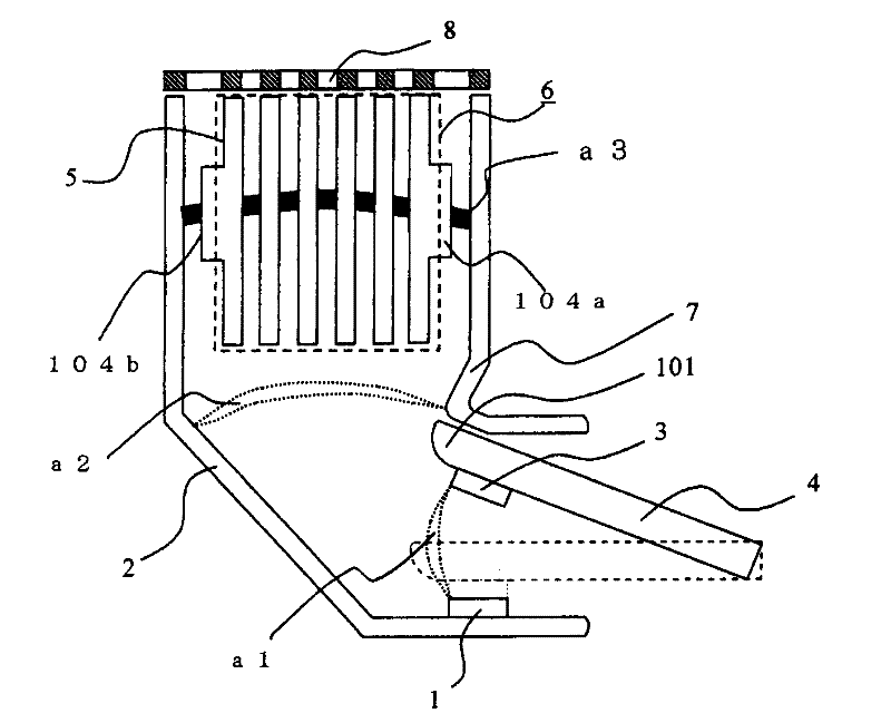
[0018] Embodiment 2 image 3 It is a drawing for explaining the arc suppression chamber of the circuit breaker of Embodiment 2, More specifically, image 3 is the side view of the arc chamber, Figure 4 is the front view of the arc extinguishing plate. Although not shown in the above figure, the arc extinguishing chamber integrally accommodates a relay unit that detects an abnormal current and outputs an opening command, a drive mechanism unit to which the command is transmitted, and the like in a container made of an insulator.

[0019] Such as image 3 As shown, the arc suppression chamber is composed of the following parts: a fixed contact side arc moving conductor 2 with a fixed contact 1; a movable contact 4, which has a movable contact 3 that is in contact with or separated from the fixed contact 1, And form a contact pair with the arc moving conductor 2 on the fixed contact side; the arc extinguishing device 6, which is composed of multiple overlapping arc extinguish...

Embodiment approach 3

[0025] Embodiment 3 Figure 5 It is a front view of the fixed-contact-side and movable-contact-side arc moving conductors 2 and 7 of the third embodiment, which are disposed opposite to both sides of the arc extinguishing device. Figure 5 The shown protruding parts 105a, 105b are composed of separate parts from the arc moving conductors 2, 7, and are separated from the two side surfaces of the arc moving conductors 2, 7 by a distance g (movable contact side arc moving conductor 7, fixed contact side arc The gap g) between the conductor side 2 and the outermost arc extinguishing plate 5 is moved, held and arranged in a frame not shown in the figure, that is, arranged outside the arc flow path, and the above frame is formed and constituted by an insulating member. Arc chamber space. By disposing in this way, the electric field at both ends of the arc extinguishing device 6 can be locally strengthened. Since the arc generated from the arc point passes through the protrusions 10...


PUM


Abstract

The present invention provides a circuit breaker which comprises a fixed contact point (1), a movable contact point (3) contacted or separated from the fixed contact point (1), an extinguishing arc mechanism (6), an arc movable conductor (2) located on a side of the fixed contact point for leading the arc to the extinguishing arc mechanism (6), and an arc movable conductor (7) located on a side of the movable contact point. The extinguishing arc mechanism (6) is formed by arranging a plurality of extinguishing arc plates (5), the extinguishing arc plates (5) switch and extinguishing arc generated between the fixed contact point (1) and the movable contact point (3) when the movable contact point (3) is separated, the arc movable conducts (2, 7) are opposite to the extinguishing arc platesby spacing preset clearance respectively. An electric field intensification part is arranged on any one or both side of the relative face of the arc movable conducts (2, 7) and the extinguishing arc plate (5) on external side.

Description

technical field [0001] The present invention relates to a circuit breaker such as a wiring circuit breaker or an earth leakage circuit breaker, and more particularly to a circuit breaker capable of improving the current limiting performance for suppressing overcurrent by improving the arc maintenance performance of the arc extinguishing plate in the arc extinguishing chamber In the circuit breaker, the arc extinguishing chamber has an arc moving conductor for moving the arc to a plurality of stacked arc extinguishing plates as arc extinguishing means. Background technique [0002] The increase in capacity and space saving of equipment for low-voltage wiring in recent years requires downsizing of external dimensions of wiring circuit breakers, earth leakage circuit breakers, and the like. Improving the current-limiting performance for suppressing overcurrent is one of the issues of miniaturization. When the overcurrent is interrupted in the event of an accident, etc., the ar...

Claims


Application Information

Patent Timeline
Patent Type & Authority Patents(China)
IPC IPC(8): H01H9/34H01H73/18
Inventor 小仓健太郎竹内敏惠吉田忠广牧田阳中川淳饭塚贵士
Owner MITSUBISHI ELECTRIC CORP
Why Eureka
Try Eureka