Driving system and method of light emitting diode with high efficacy of power consumption

A technology of light emitting diode and driving system

Active Publication Date: 2010-01-13
HIMAX DISPLAY INC
View PDF0 Cites 7 Cited by
  • Summary
  • Abstract
  • Description
  • Claims
  • Application Information

AI Technical Summary

Problems solved by technology

Although the LED current (and its brightness) driven by the traditional constant current will not change with the change of the forward voltage VF, the LED needs to be connected in series with the current-sensing resistor, which also causes waste of power consumption
[0005] In view of the waste of power consumption caused by the traditional constant voltage or constant current driving method, it is urgent to propose a new driving mechanism, which can not only increase the efficiency of power consumption, but also maintain the stability of the driving current

Method used


Image

  • Driving system and method of light emitting diode with high efficacy of power consumption
  • Driving system and method of light emitting diode with high efficacy of power consumption
  • Driving system and method of light emitting diode with high efficacy of power consumption

Examples


Embodiment Construction

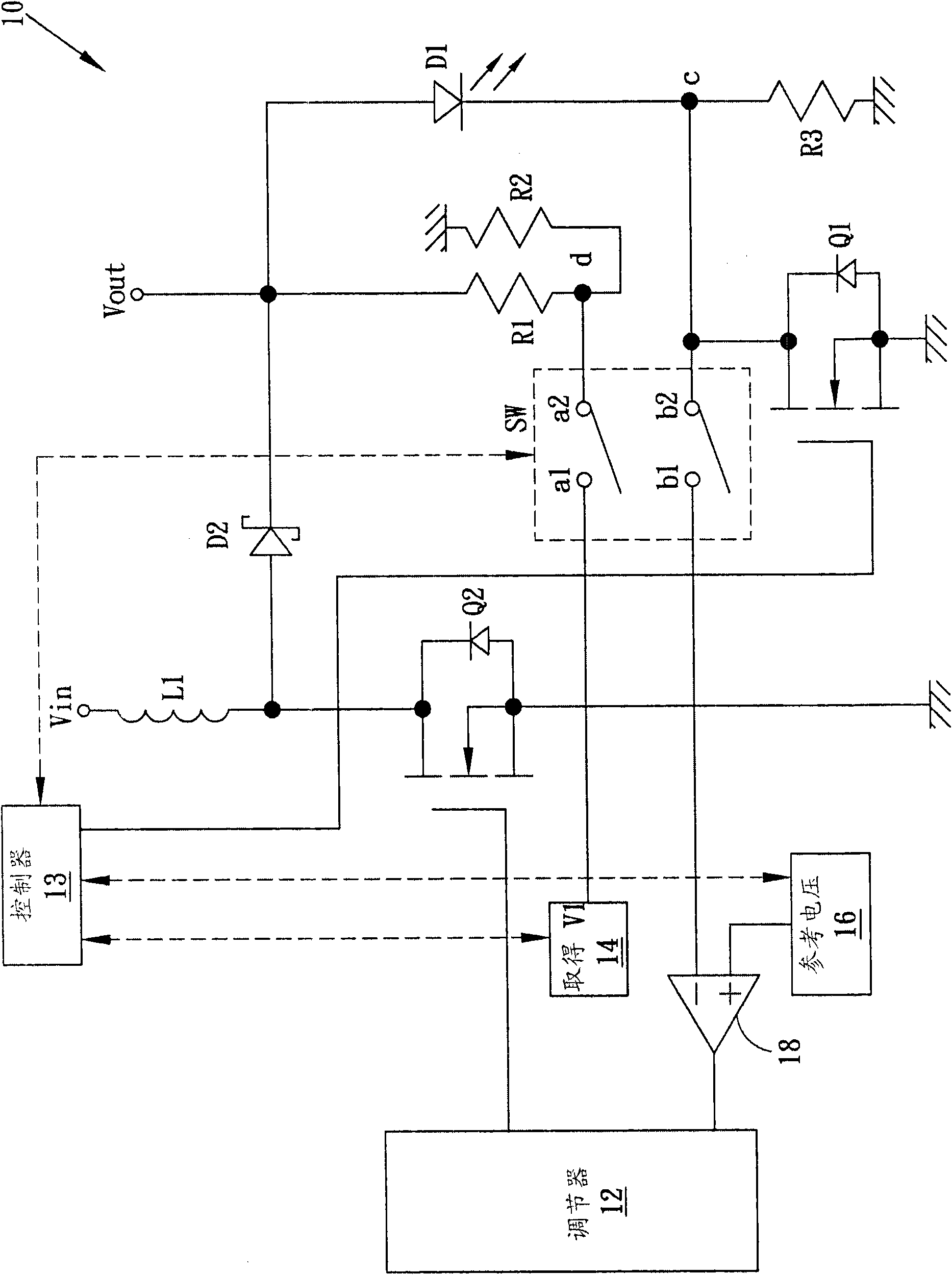
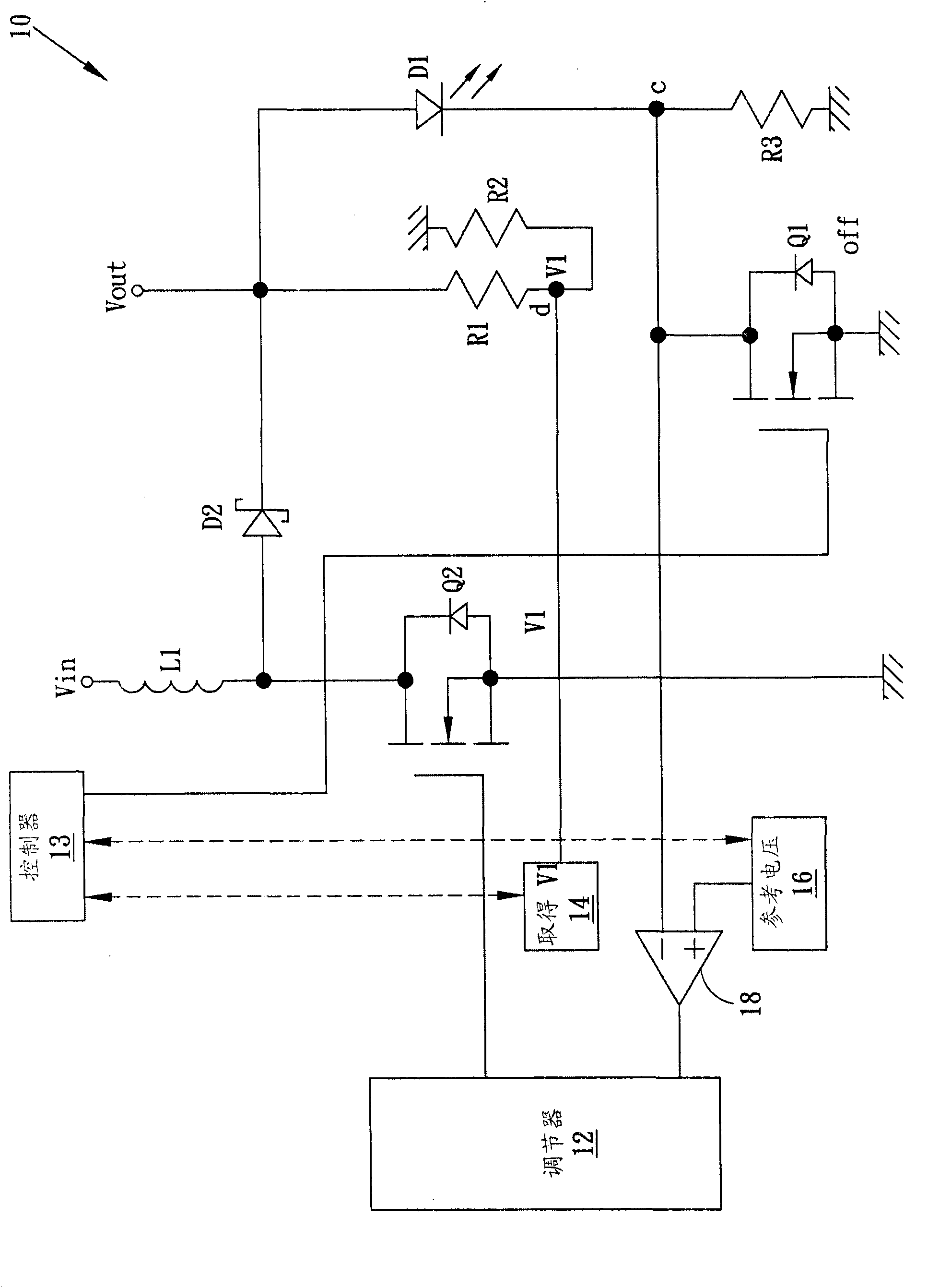
[0029] figure 2 A light emitting diode (LED) driving system 10 of an embodiment of the present invention is shown. Although this embodiment uses one LED as an illustration, those skilled in the art can use multiple LEDs, and these LEDs can be connected in series or in parallel. In this embodiment, the regulator (regulator) 12 sequentially turns on (on) and turns off (off) (switching) the transistor Q2 sequentially, so that the supply voltage Vin can store energy in the inductor L1 when the transistor Q2 is turned on, and then When the transistor Q2 is turned off, the stored energy is transferred to the output voltage terminal Vout of the LED D1. The rectifying diode D2 is used to prevent the current of the output voltage terminal Vout from flowing back to the supply voltage Vin. The switching duty cycle of the regulator 12 is changed according to the output of the error comparator (error comparator) 18 . For example, when the output of the error comparator 18 increases (wh...


PUM


Abstract

The invention relates to a driving system and a method of a light emitting diode. The system is sequentially switched between a constant current mode and a constant voltage mode. Thus, the straight-forward voltage of the light emitting diode is maintained at a fixed value, and the efficacy of the power consumption of the light emitting diode is increased.

Description

technical field [0001] The present invention relates to the driving of light-emitting diodes (LEDs), in particular to an LED driving system and method with high power consumption efficiency. Background technique [0002] Light emitting diodes (LEDs) are commonly used in various electronic devices and have various applications. For example, LEDs can be used in a backlight module of a liquid crystal display (LCD) to provide a backlight, or in a charge-coupled device (CCD) camera to provide flash illumination. LED is actually a temperature-dependent component, in other words, the characteristics of LED will change with the change of temperature. figure 1 Shows LEDs and their equivalent circuits. An LED is equivalent to a voltage source connected in series with a negative-temperature-coefficient (NTC) resistor. When the current through the LED causes the temperature to rise, the resistance of the NTC resistor will decrease, and vice versa. Therefore, when the current passing...

Claims


Application Information

Patent Timeline
Patent Type & Authority Applications(China)
IPC IPC(8): H05B37/02
Inventor 陈进荣
Owner HIMAX DISPLAY INC
Why Eureka
Try Eureka