Two-stage rotary type expander, expander-integrated compressor, and refrigeration cycle device
A circulatory device, expander technology, applied in the direction of rotary piston machinery, rotary piston engine, compressor, etc., can solve the problem of pulsation and other problems, and achieve the effect of suppressing pulsation
- Summary
- Abstract
- Description
- Claims
- Application Information
AI Technical Summary
Problems solved by technology
Method used
Image

Examples
Embodiment approach 1
[0050] "Structure of expander-integrated compressor"
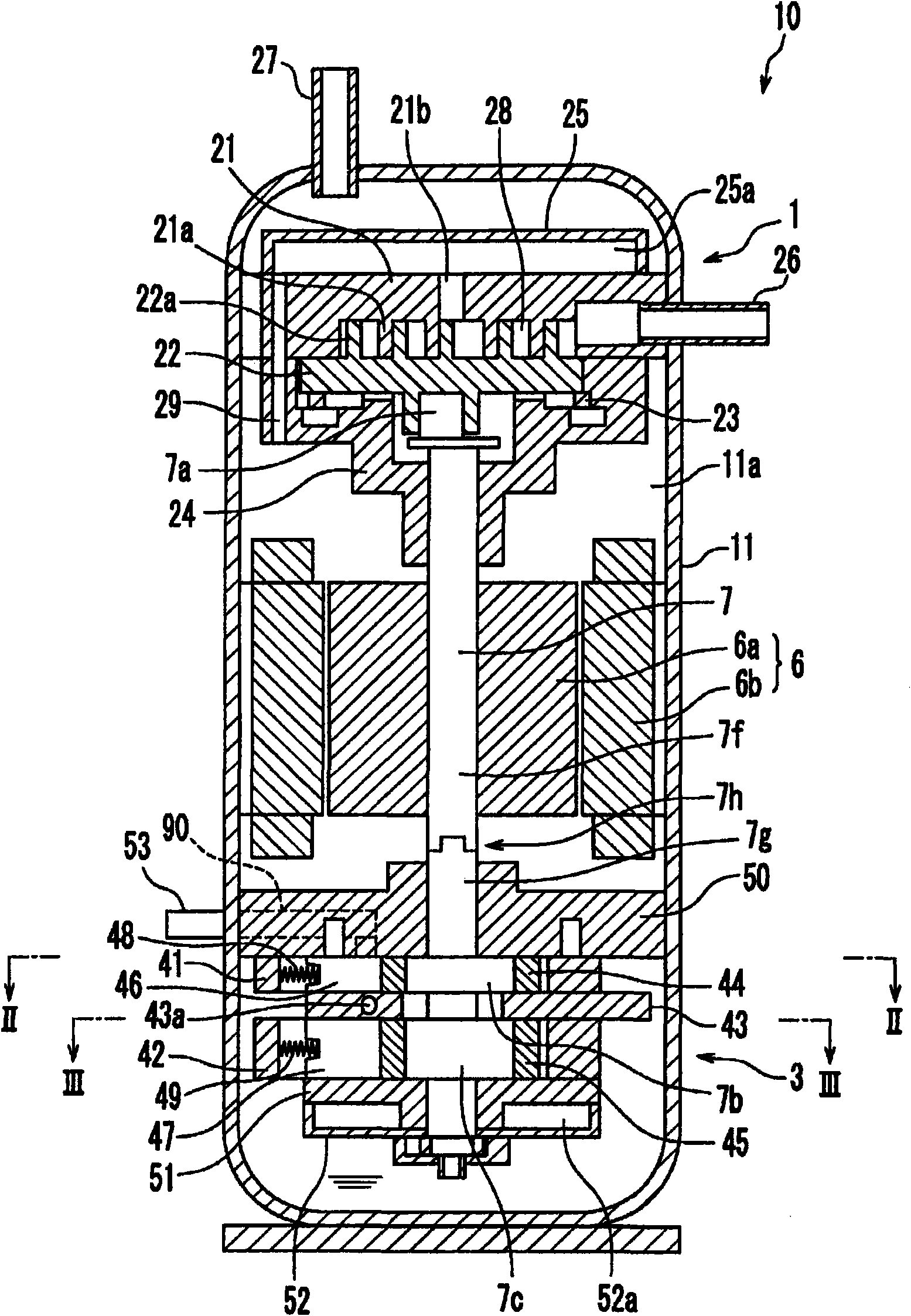
[0051] Such as figure 1 As shown, the expander-integrated compressor 10 according to the present embodiment includes: an airtight container 11 ; a scroll-type compression mechanism 1 disposed on the upper side in the airtight container 11 ; Stage rotary expansion mechanism3. A rotary electric motor 6 including a rotor 6 a and a stator 6 b is disposed between the compression mechanism 1 and the expansion mechanism 3 . The compression mechanism 1 , the rotor 6 a of the rotary motor 6 , and the expansion mechanism 3 are connected by a rotary shaft 7 .
[0052] The compression mechanism 1 has: a fixed scroll 21 , an orbiting scroll 22 , an Oldham ring 23 , a bearing member 24 , and a muffler 25 . A suction pipe 26 and a discharge pipe 27 are connected to the airtight container 11 . The orbiting scroll 22 is fitted to the eccentric shaft 7 a of the rotary shaft 7 , and its rotational movement is restricted by an Oldham ring...
Embodiment approach 2
[0092] Embodiment 2 is an embodiment in which the suction hole 71 of the expansion mechanism 3 is modified. Since it is the same as Embodiment 1 except for the suction hole 71, description thereof will be omitted.
[0093] Such as Figure 11A and Figure 11B As shown, in Embodiment 2, the suction hole 71 of the expansion mechanism 3 is formed in the upper end plate 50 . That is, in the second embodiment, the downstream end of the suction passage 90 formed on the upper end plate 50 faces the working chamber in the first cylinder 41, and the downstream end of the suction passage 90 ( Figure 11Amiddle lower end) becomes the suction hole 71. The suction hole 71 opens downward toward the working chamber in the first cylinder 41 .
[0094] In this embodiment, the communication path 43a is in a non-communicating state with the upstream first working chamber 55a or the downstream first working chamber 55b communicating with the suction hole 71 during the suction process, and is i...
Embodiment approach 3
[0098] Embodiment 3 is also a mode in which the suction hole 71 of the expansion mechanism 3 is changed in Embodiment 1. Since it is the same as Embodiment 1 except for the suction hole 71, description thereof will be omitted.
[0099] Such as Figure 12A and Figure 12B As shown, in the third embodiment, the suction hole 71 of the expansion mechanism 3 is formed across the first cylinder 41 and the upper end plate 50 . That is, in the third embodiment, the suction hole 71 is formed by the hole 71d formed by the longitudinal groove formed in the inner peripheral surface of the first cylinder 41 and the hole 71c formed in the upper end plate 50 . The hole 71 d opens radially inward toward the working chamber in the first cylinder 41 , and the hole 71 c opens downward toward the working chamber in the first cylinder 41 .
[0100] Also in this embodiment, the communication passage 43a is formed so as not to communicate with the working chambers 55a and 55b during the suction p...
PUM
 Abstract
Description
Claims
Application Information
 - R&D
- Intellectual Property
- Life Sciences
- Materials
- Tech Scout
- Unparalleled Data Quality
- Higher Quality Content
- 60% Fewer Hallucinations
Browse by: Latest US Patents, China's latest patents, Technical Efficacy Thesaurus, Application Domain, Technology Topic, Popular Technical Reports.
© 2025 PatSnap. All rights reserved.Legal|Privacy policy|Modern Slavery Act Transparency Statement|Sitemap|About US| Contact US: help@patsnap.com