Automobile intelligent alarm system
An intelligent alarm and automobile technology, applied in alarms, vehicle parts, anti-theft vehicle accessories, etc., can solve problems such as installation, high service costs, few applications in ordinary families, easy to be intercepted or crack passwords, etc., to achieve Save the cost of use, improve intelligence and safety, and facilitate the application
- Summary
- Abstract
- Description
- Claims
- Application Information
AI Technical Summary
Problems solved by technology
Method used
Image
Examples
Embodiment 1
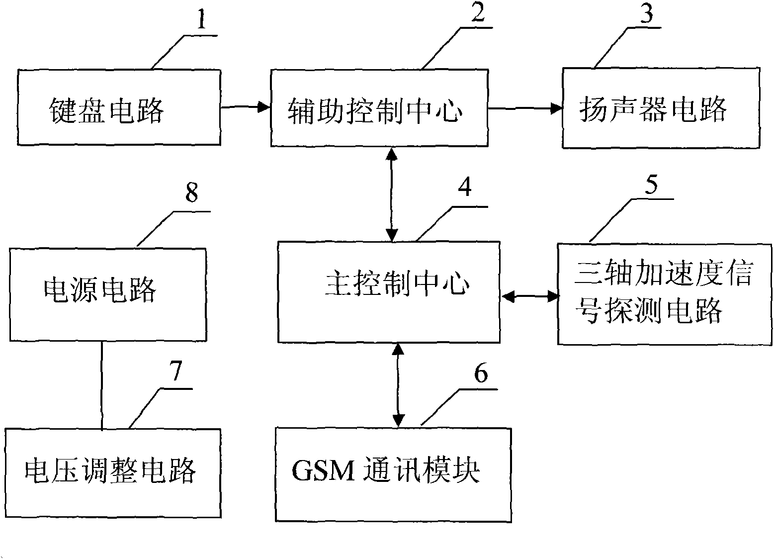
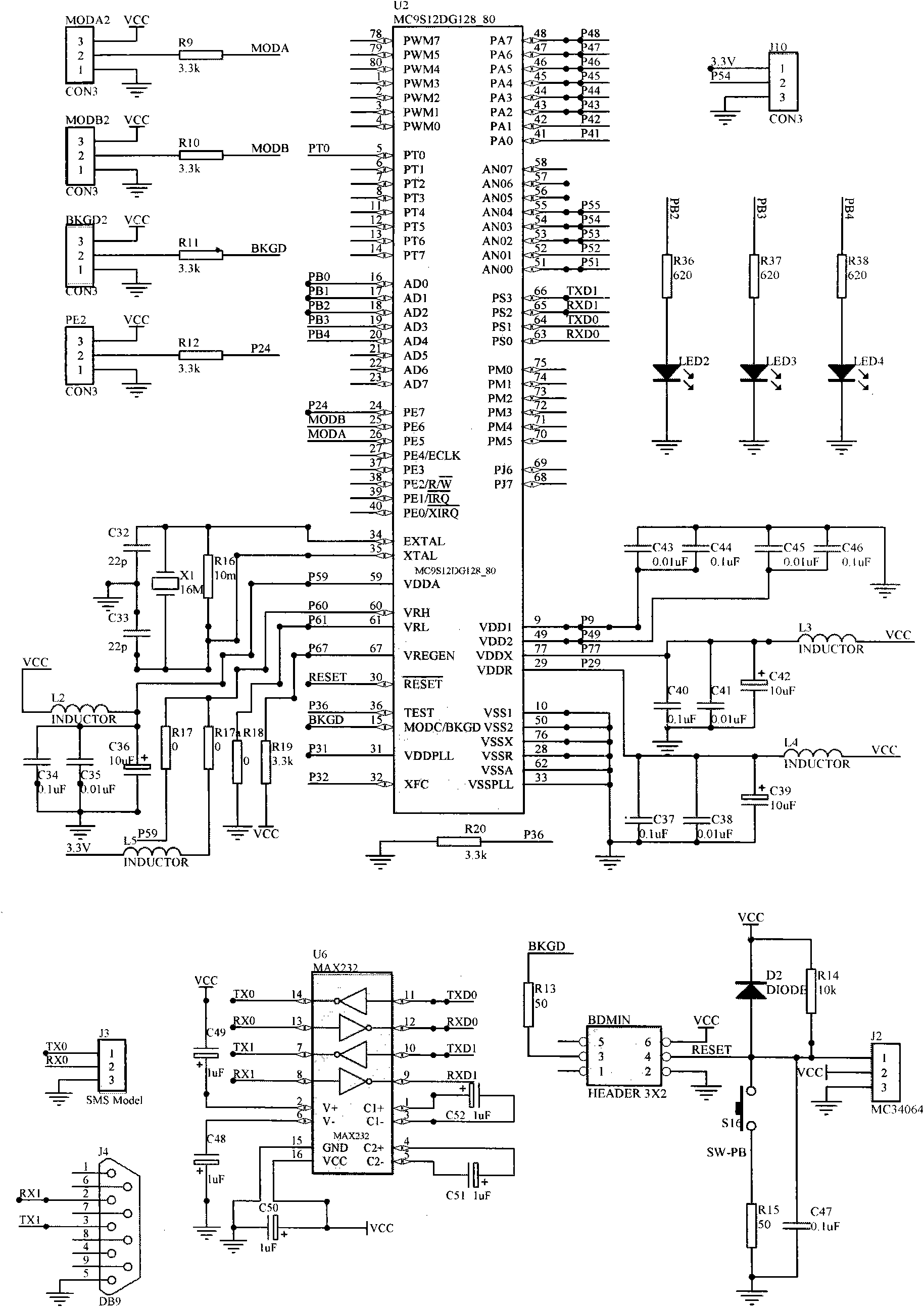
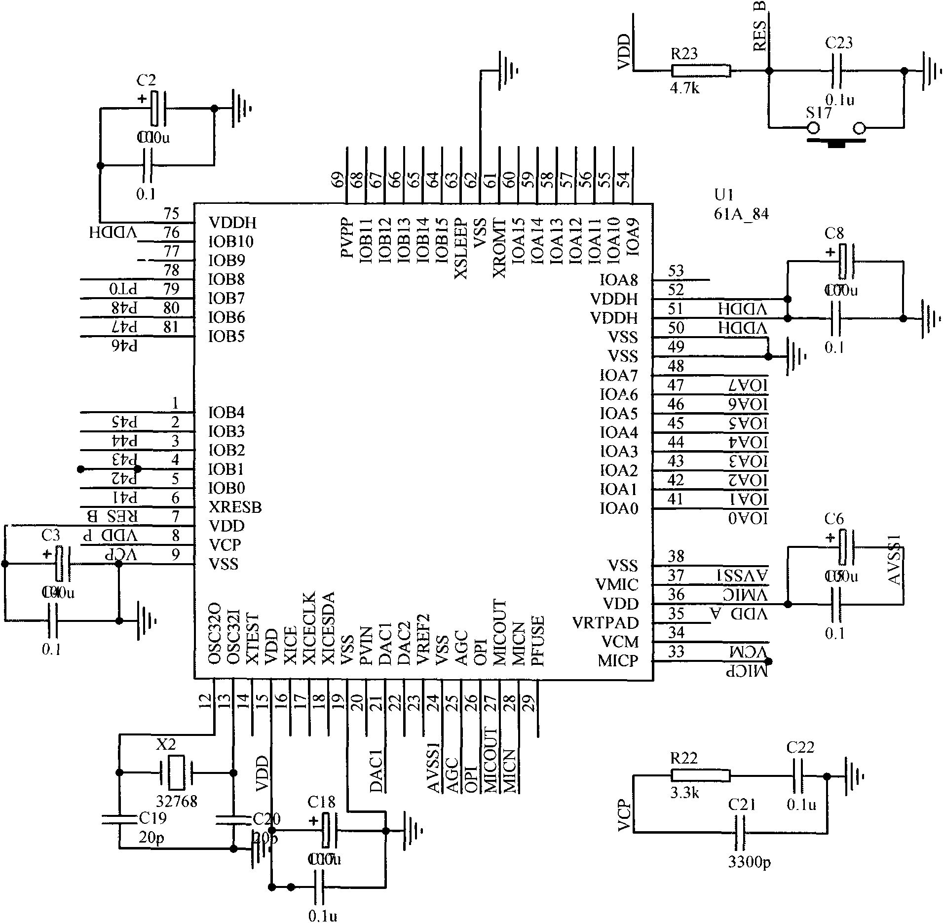
[0037] Such as figure 1 As shown, an automobile intelligent alarm system is composed of a keyboard circuit 1, an auxiliary control center 2, a main control center 4, a three-axis acceleration signal detection circuit 5, a GSM communication module 6, a voltage adjustment circuit 7 and a power supply circuit 8; the main control The center 4 is connected with the auxiliary control center 2, the triaxial acceleration signal detection circuit 5 and the GSM communication module 6, the auxiliary control center 2 is connected with the keyboard circuit 1, the input end of the voltage adjustment circuit 7 is connected with the power supply circuit 8, and the output The terminals are connected with each circuit and module, the main control center 4 and the auxiliary control center 2. The system can also be provided with a loudspeaker circuit 3 which is connected to the auxiliary control center 2 . The main control center 4 is provided with a main control program, and the auxiliary contr...
Embodiment 2
[0040] The working method of the intelligent alarm system described in embodiment 1 is: the vibration signal of triaxial acceleration signal detection circuit 5 gathering car body, as Figure 8 As shown, the main control program of the main control center 4 analyzes and processes the vibration signal according to the following steps:
[0041] Step 1: Receive the vibration signal input by the triaxial acceleration signal detection circuit 5 .
[0042] Step 2: Power on the auxiliary control center 2 and the GSM communication module 6 by applying a high level to the base of the switching transistor in the voltage adjustment circuit 7 .
[0043] Step 3: Digitally filter the vibration signal to eliminate various interferences added to the signal.
[0044] Step 4: Analyze the direction of each axis on the vibration signal to determine the force direction of the car body. The main control program defines 26 directions, and Figure 9 shows a schematic diagram of 19 directions, and the ...
PUM
 Abstract
Description
Claims
Application Information
 - R&D
- Intellectual Property
- Life Sciences
- Materials
- Tech Scout
- Unparalleled Data Quality
- Higher Quality Content
- 60% Fewer Hallucinations
Browse by: Latest US Patents, China's latest patents, Technical Efficacy Thesaurus, Application Domain, Technology Topic, Popular Technical Reports.
© 2025 PatSnap. All rights reserved.Legal|Privacy policy|Modern Slavery Act Transparency Statement|Sitemap|About US| Contact US: help@patsnap.com


