Fixed quantity supply device

A dosing, housing technology used in transport and packaging, loading/unloading, etc. to solve problems such as obstruction of valve rotation, inappropriateness, and reduced processing capacity

Active Publication Date: 2010-01-20
NIHON BOORUBARUBU
View PDF0 Cites 2 Cited by
  • Summary
  • Abstract
  • Description
  • Claims
  • Application Information

AI Technical Summary

Problems solved by technology

[0004] However, when the quantitative supply device described in the above-mentioned Patent Document 1 handles a highly viscous object to be transferred (such as sewage sludge, etc.), the object to be transferred tends to stick to the small chamber of the valve, which may reduce its processing capacity.
In addition, as a method of peeling off the transfer object stuck in the small chamber, a method of applying vibration or impact to the valve can also be considered, but it is not suitable for a valve that is always rotating.
[0005] In addition, in the quantitative supply device described in the above-mentioned Patent Document 1, since the valve rotates, the object to be transferred tends to enter the clearance space between the valve and the casing and solidify, possibly hindering the rotation of the valve.
In addition, it is also conceivable to separately install a part buried in the above-mentioned gap space so that the object to be transferred does not enter the above-mentioned gap space, but as a result, the object to be transferred tends to enter between this part and the valve and solidify, so fundamentally cannot be obtained. the solution

Method used


Image

  • Fixed quantity supply device
  • Fixed quantity supply device
  • Fixed quantity supply device

Examples


Embodiment Construction

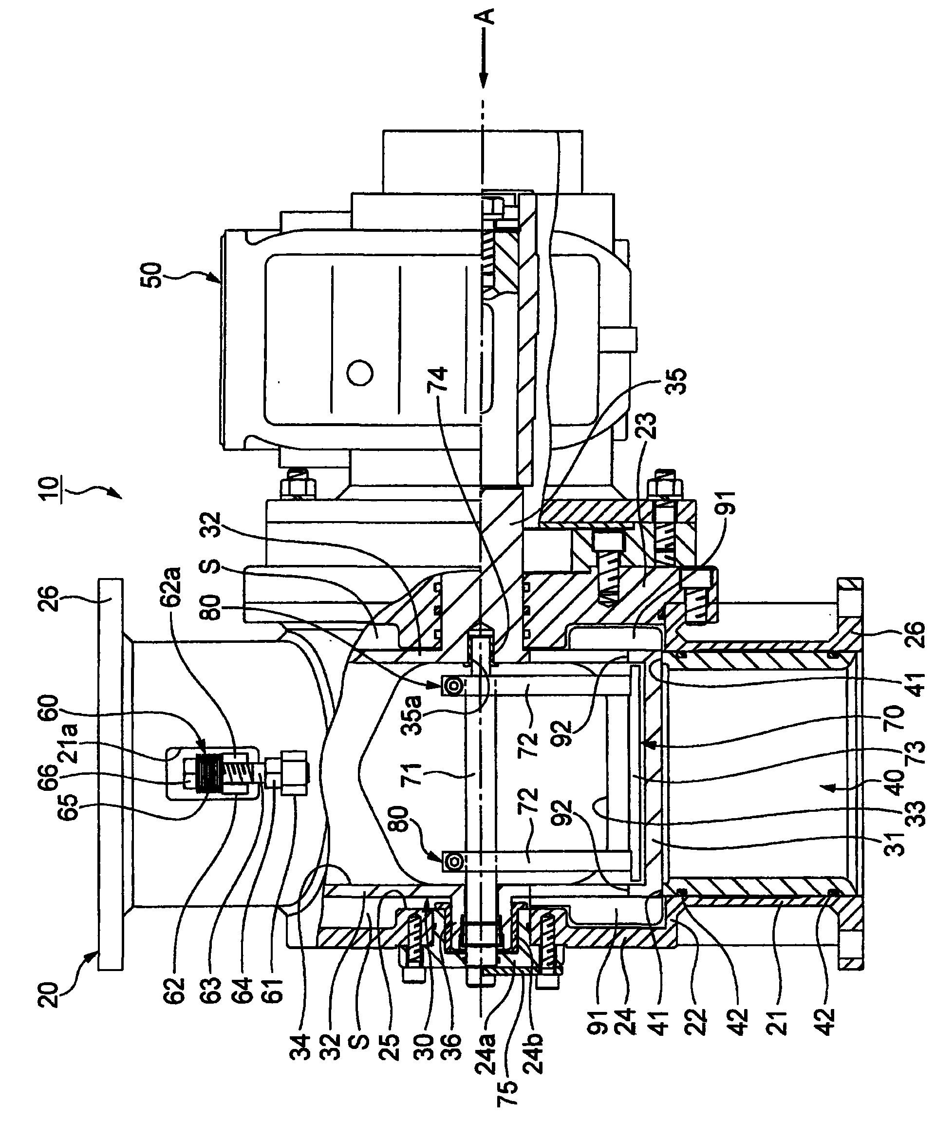
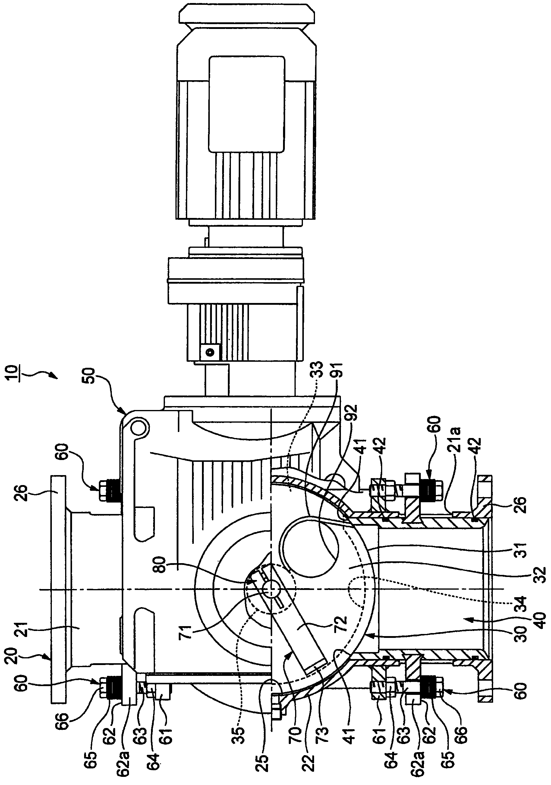
[0055] Next, an embodiment of the quantitative supply device of the present invention will be described in detail with reference to the drawings. In addition, in this embodiment, the quantitative supply device whose to-be-transferred object is powder is taken as an example and demonstrated.

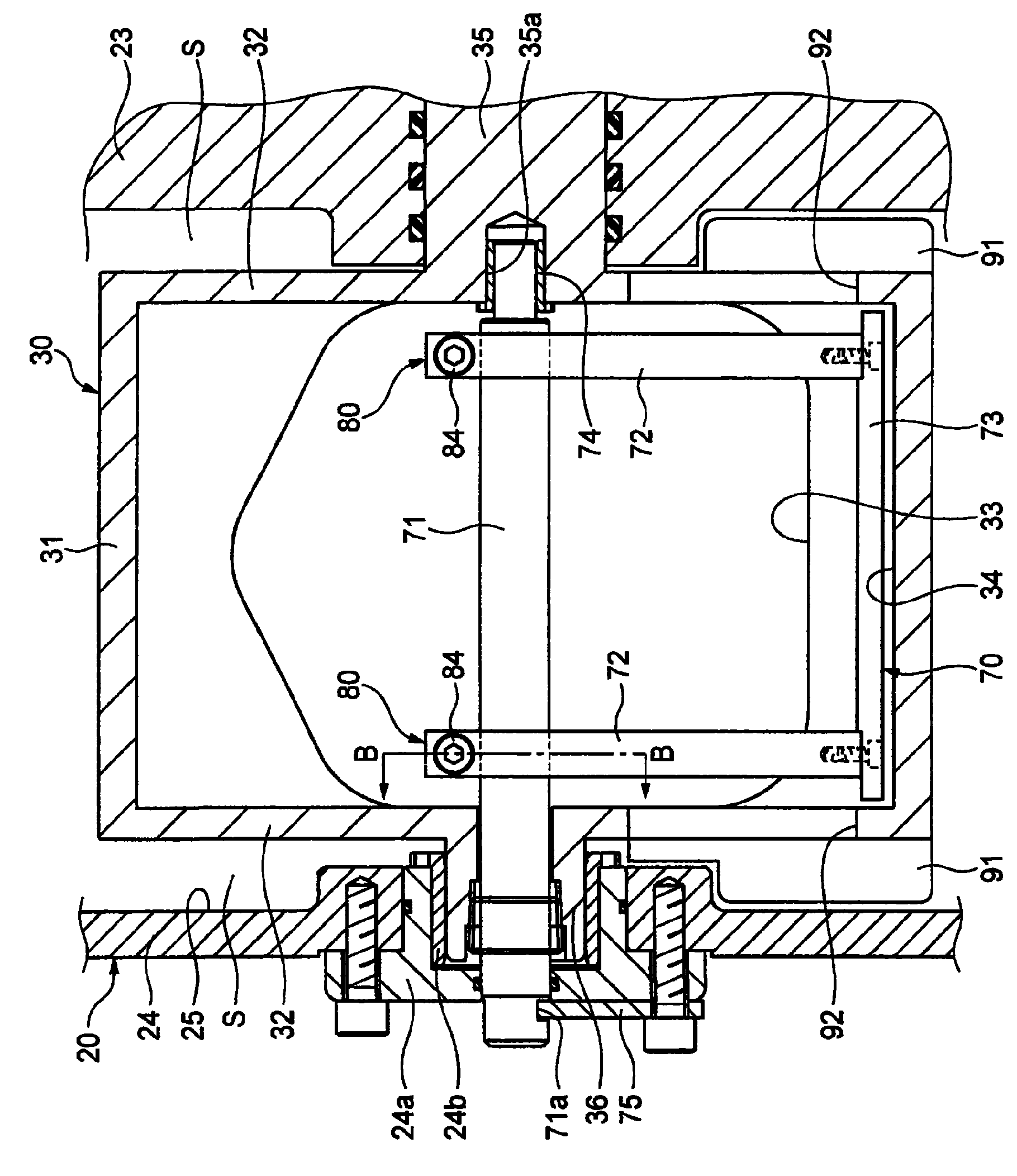
[0056] Such as figure 1 and figure 2 As shown, the quantitative supply device 10 of the present embodiment is provided with: a cylindrical housing 20, which is arranged in the housing 20, and can be arranged around the first and second rotating shafts 35, 36 arranged to cross the direction of the cylindrical axis of the housing 20. The core rotation valve 30 is inserted into both sides of the casing 20 in the direction of the cylindrical axis, and a pair of seat rings 40 are in close contact with the valve 30 for sealing. Drive device 50 .

[0057] The casing 20 includes: a first cylindrical portion 21 as a powder transfer path; Part 22, one end portion of the second cylindrical port...


PUM


Abstract

The invention provides a fixed quantity supply device capable of preventing the materials transported adhering in the chamber of a valve, and further provides a fixed quantity supply device capable of preventing the curing of the materials transported in the space between a valve and a casing to maintain the rotation of the valve. The fixed quantity supply device (10) comprises a valve (30) rotatably arranged in a casing (20) and having a chamber (34) importing the materials transported, a pair of base rings (40) embedded in two sides of the casing (20) and sealed with the valve (30) for sealing. A clapper (70) is arranged in the chamber (34) of the valve (30) to clap the material transported in the chamber (34) and provided with a shaft (71) concentrically inserted with a rotating shaft (36) of the valve (30) and fixed with the casing (20) at one end, a pair of arms (72) supported by the shaft (71) and a clapper part (73) fixed at the front ends of the arms (72). A rotation allowable mechanism (80) is provided between the shaft (71) and arms (72) to rotate the valve when the load on the arms exceeds the prescribed load. The valve (30) is provided with a blade (91) collecting the materials transported in the space (S) between the valve (30) and the casing (20) and an import opening (92) importing the materials transported from the blade (91) to the chamber (34).

Description

technical field [0001] The present invention relates to a quantitative supply device, for example, in a chemical plant, a food factory, etc., which supplies a predetermined amount of objects to be transferred (such as powder, etc.) from a supply device such as a hopper to a pipe of a conveyance path. Background technique [0002] As an existing quantitative supply device, it is known to have a cylindrical casing, which is arranged in the casing so as to be rotatable around a rotating shaft arranged to cross the direction of the cylindrical axis of the casing, and has a device for introducing the object to be transferred. A small chamber valve, a quantitative supply device for a pair of seat rings that are inserted on both sides of the cylindrical axis direction of the housing and are in close contact with the valve to seal it. A pair of side panels of the part, and an opening formed on the peripheral surface of the cylindrical part. In addition, the above-mentioned conventi...

Claims


Application Information

Patent Timeline
Patent Type & Authority Applications(China)
IPC IPC(8): B65G65/48
Inventor 竹内也寸志田中雅裕
Owner NIHON BOORUBARUBU
Why Eureka
Try Eureka