
System and method for determining thin-film stress based on deformation measurement and numerical reverse

A technology of film stress and measurement value, applied in the direction of measuring force, measuring device, instrument, etc., can solve the problems of difficult measurement, not considering the coordination conditions between the substrate and the film, and unable to measure the kinematic variables of all nodes.

Inactive Publication Date: 2010-01-20
付康
View PDF0 Cites 27 Cited by
  • Summary
  • Abstract
  • Description
  • Claims
  • Application Information

AI Technical Summary

Problems solved by technology

Although this method avoids the problem of using non-coordinated strains, it still has the following obvious defects: (1) It is generally impossible to measure the kinematic variables of all nodes. Except for the nodes on the boundary, the internal nodes are not measurable. It can only be obtained by interpolation; (2) It is difficult to ensure sufficient accuracy in the measurement of degrees of freedom such as rotation angles; (3) The coordination condition between the deformation of the substrate and the film is not considered; (4) The calculation needs to use the material parameters of the film; and (5) The influence of correcting external forces (such as self-weight) on the measured deformation is not considered

Method used

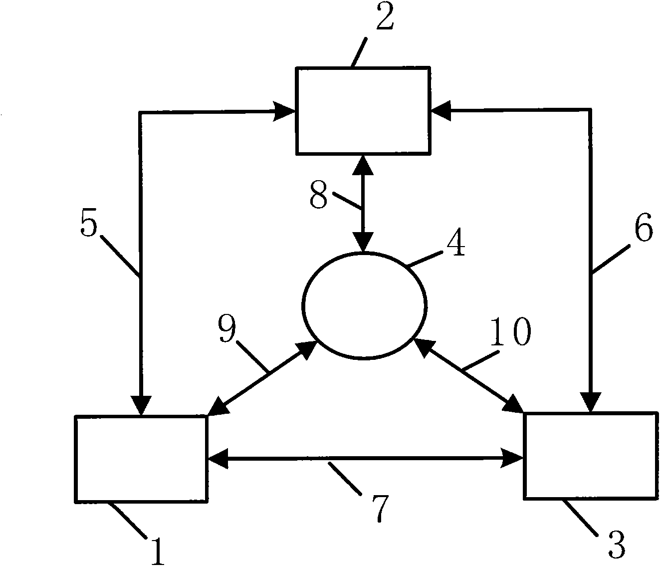
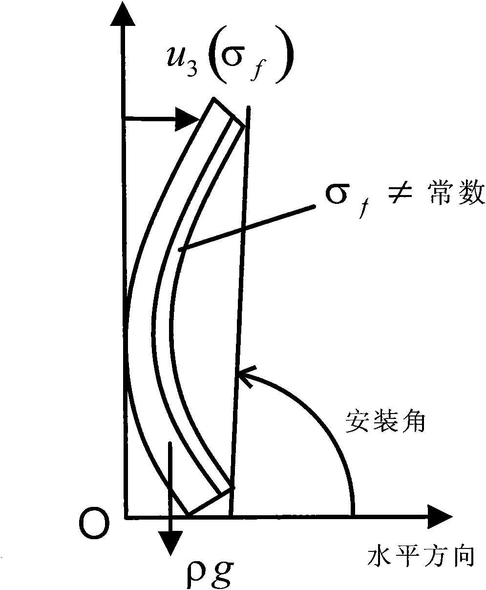
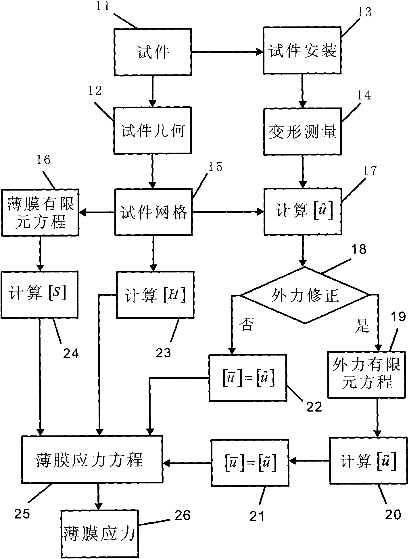

Image

  • System and method for determining thin-film stress based on deformation measurement and numerical reverse
  • System and method for determining thin-film stress based on deformation measurement and numerical reverse
  • System and method for determining thin-film stress based on deformation measurement and numerical reverse

Examples


Embodiment Construction

[0056] Illustrate the embodiment of the present invention by example below: Consider a rectangular base material (such as Figure 6 shown), its size is 30mm×20mm×70μm, Young’s modulus is 290GPa, Poisson’s ratio is 0.32, density is 2.3290g / cm 3 . A transverse film band with a width of 2 mm and a thickness of 0.7 µm was formed at a distance of 12 mm from the left boundary in the longitudinal direction. The film stress prediction steps are as follows:

[0057] (1) The user installs the substrate without film and the film material with film respectively on the measuring platform along the given direction;

[0058] (2) Measure the profile data of the matrix when there is no film and the profile data of the matrix when there is a film, respectively, with a shape measuring device;

[0059] (3) compare the shape data obtained by two kinds of measurements with a calculation program to obtain the change amount of the film material profile;

[0060] (4) Carry out geometric modeling a...


PUM


Abstract

The invention provides a simple, flexible and reliable thin-film stress measuring system and a measuring method. The invention adopts shape-measuring equipment to measure the deformation of a thin-film material caused by thin-film stress, and expresses the deformation as the deflection or the cross-section corner of the thin-film material. The invention adopts a plate structural finite element to discrete the geometric model of a detected object, so as to give all or part of measuring values of the nodal freedom degree of the finite element in a direct measurement or indirect interpolation mode, when data are measured and processed, the influence of external force on deformation measurement is modified. The least-squares fitting condition between the deformation generated by the thin-film stress at the nodes and the deformation given by measurement is established to reversely calculate the thin-film stress by regularization process. In the condition of irregular plane form, uneven thickness of a sample and the thin-film, uncertain parameters of the thin-film material, the invention can be used for identifying anisotropic and non-uniformly distributed thin-film stress.

Description

technical field [0001] The invention pertains to measurement techniques used in the manufacture of integrated circuits and micro-electromechanical systems (MEMS), which are used to measure thin-film stress in thin-film materials. Background technique [0002] Thin film materials are widely used in the manufacture of integrated circuits and microelectromechanical systems (MEMS). After chemical deposition (CVD) and physical deposition (PVD) techniques are used to form thin film materials with specific properties and functions on the surface of the substrate, the thin film materials can be processed into integrated circuits and microchips by using micromachining processes such as masks, photolithography, and corrosion. structure. Non-negligible stress inevitably occurs in the thin film material due to the crystal defects generated during the film formation process and the difference between the thermal expansion coefficients of the thin film material and the base material. Th...

Claims


Application Information

Patent Timeline
IPC IPC(8): G01L1/00G01B11/16
Inventor 付康
Owner 付康
Learn More