Fluorescent lamp having bulb whose end portion to which stem mount is welded, and a lighting apparatus having the fluorescent lamp

A technology for lighting devices and welding parts, which is applied in the direction of fluorescence, lighting devices, parts of lighting devices, etc., can solve the problems of reduced brightness in the end area and differences in bulbs, and achieve the effect of reducing the difference in brightness

Inactive Publication Date: 2010-01-20
PANASONIC CORP
View PDF3 Cites 0 Cited by
  • Summary
  • Abstract
  • Description
  • Claims
  • Application Information

AI Technical Summary

Problems solved by technology

Therefore, it was found that according to conventional seamless fluorescent lamps, unfortunately, the brightness is reduced in the end regions and a difference is produced between the central part and the end parts of the bulb in the longitudinal direction.

Method used


Image

  • Fluorescent lamp having bulb whose end portion to which stem mount is welded, and a lighting apparatus having the fluorescent lamp
  • Fluorescent lamp having bulb whose end portion to which stem mount is welded, and a lighting apparatus having the fluorescent lamp
  • Fluorescent lamp having bulb whose end portion to which stem mount is welded, and a lighting apparatus having the fluorescent lamp

Examples


Embodiment Construction

[0028] The best embodiments for carrying out the present invention are described below using examples. Note that the embodiments described hereinafter are only examples for explaining the structure, function and effect of the present invention, so the present invention is by no means limited to the following embodiments as long as it does not depart from the scope of essential characteristics of the present invention.

[0029] 1. Structure of fluorescent lamp 1

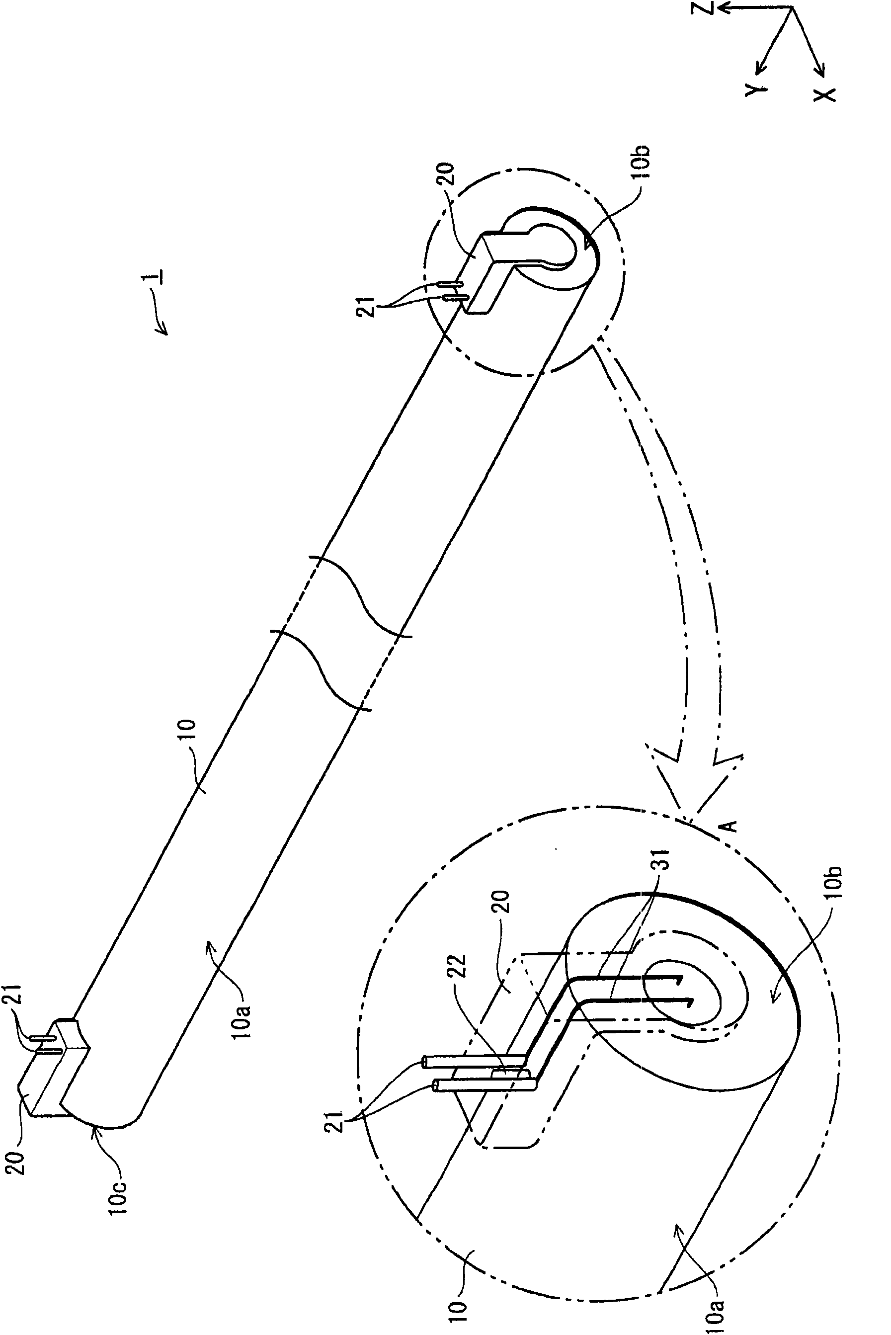
[0030] Reference to the structure of the fluorescent lamp 1 belonging to the embodiment of the present invention figure 2 describe.

[0031] like figure 2 As shown, the fluorescent lamp 1 pertaining to the embodiment has a cylindrical glass bulb 10 whose tube axis is in the Y-axis direction and a base is provided at each end portion of the bulb 10 in the Y-axis direction. The base 20 at each end portion has two base pins 21 extending outward in the Z-direction intersecting the tube axis (Y-axis) of the glass bulb 1...


PUM


Abstract

A fluorescent lamp has a bulb, a phosphor layer and a base. The bulb has a tubular portion and an axially-opposed end portions to each of which a stem mount is welded. Each stem mount has an electrode. Each end portion has a ring-shaped end wall and a portion for welding the stem mount located radially inward from an inner edge of the end wall. The phosphor layer is formed on an inner surface of the tubular portion. The base is provided to cover the stem mount. The base, in outside diameter, is smaller than the bulb and larger than the stem mount such that the end wall of the bulb is exposed.

Description

technical field [0001] The present invention relates to a fluorescent lamp and a lighting device having the fluorescent lamp having a bulb with a socket welded to each end portion of the bulb. Background technique [0002] Fluorescent lamps are widely used for home, office and workplace lighting. This is because fluorescent lamps have higher light efficiency than incandescent lamps and emit light with high color reproducibility. The fluorescent lamp has a structure in which a fluorescent layer is formed on an inner wall of a cylindrical glass bulb and each end of the bulb is sealed by a stem. The lead is inserted into the stem, and the electrode is connected to the lead at its end portion within the glass bulb. In addition, the lead wires extending outward from the glass bulb are connected to the base pins, and the base pins are fixed to extend outward in the direction of the tube axis of the glass bulb. [0003] When a plurality of fluorescent lamps having the above-desc...

Claims


Application Information

Patent Timeline
Patent Type & Authority Applications(China)
IPC IPC(8): H01J61/00H01J61/36H01J61/42
CPCH01J61/70H01J61/363H01J5/50F21V19/008F21Y2103/00F21S2/00
Inventor 饭田史朗内田纪幸长浜功幸田中裕美三贵政弘
Owner PANASONIC CORP
Why Eureka
Try Eureka