Electronic rectifier of fluorescent lamp

An electronic rectification, fluorescent lamp technology, applied in the direction of high-efficiency power electronic conversion, light source, electric light source, etc., can solve the problems of impossibility, poor electromagnetic interference resistance, low lumen coefficient, etc., to reduce interference, reduce reactive power loss, improve Effect of Lumen Factor

Inactive Publication Date: 2010-01-20
上海美丽灯饰有限公司
View PDF0 Cites 1 Cited by
  • Summary
  • Abstract
  • Description
  • Claims
  • Application Information

AI Technical Summary

Problems solved by technology

For the electronic rectifier of this structure, there is no circuit for correcting the power factor, so this circuit is often poor in a

Method used


Image

  • Electronic rectifier of fluorescent lamp
  • Electronic rectifier of fluorescent lamp

Examples


Embodiment

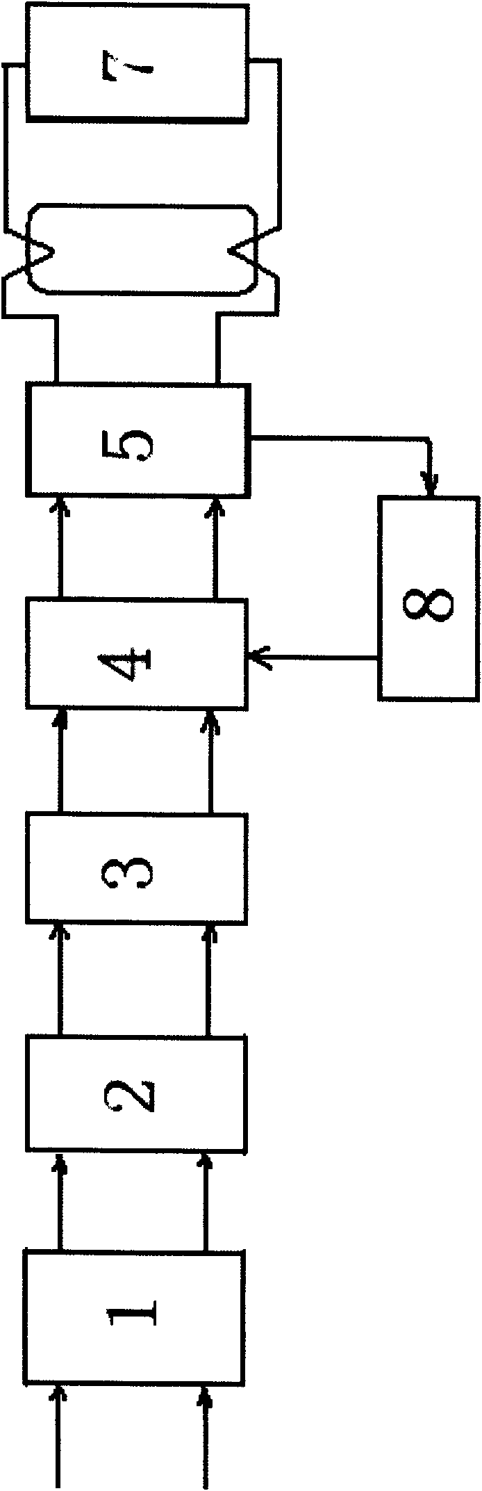
[0011] Such as figure 1 Shown is a circuit block diagram of a fluorescent lamp electronic rectifier provided by the present invention, including a bridge rectifier circuit 2 and a starting circuit 4, the starting circuit 4 is connected in series with a high-frequency inverter circuit 5 and a starter circuit 7 in sequence, and the starting circuit 4 and the starting circuit 7 are connected in series. An abnormal protection automatic recovery circuit 8 is connected across the high-frequency inverter circuit 5, and a power factor main correction circuit 3 with power feedback is connected between the bridge rectifier circuit 2 and the start-up circuit 4. An auxiliary power factor correction circuit 1 is provided between the formula rectification circuits 2 .

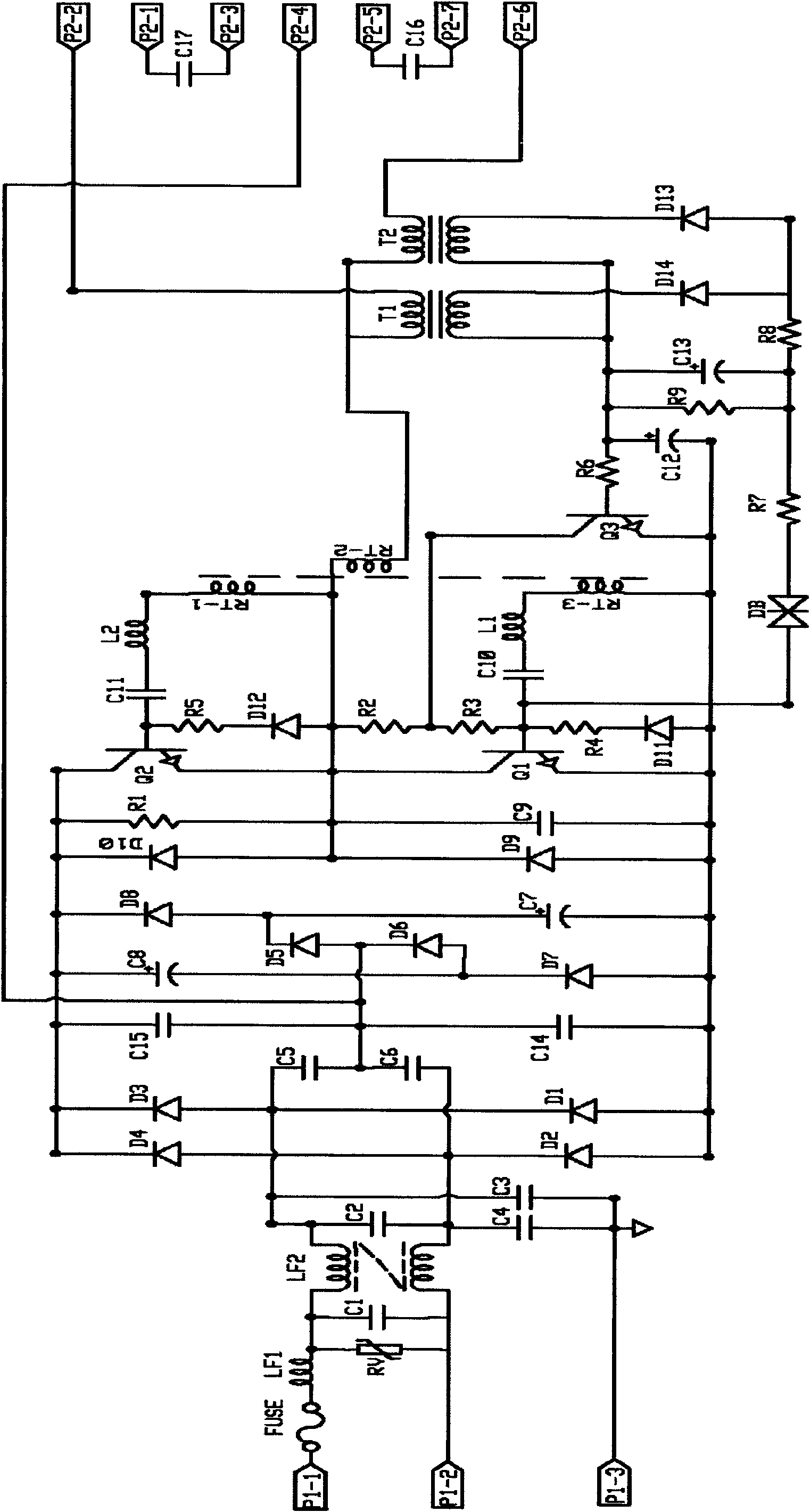
[0012] Such as figure 2 As shown, it is an electrical schematic diagram of an electronic rectifier for a fluorescent lamp provided by the present invention. The power factor auxiliary correction circuit 1 includes a filter...


PUM


Abstract

The invention relates to an electronic rectifier, comprising a shell and an electronic circuit arranged in the shell; wherein the electronic circuit comprises a bridge type rectifier circuit and a starting circuit which is in serial connection with a high frequency contravariant circuit and a starter circuit, an abnormal protection automatic restoration circuit is bridge-jointed between the starting circuit and the high frequency contravariant circuit; the invention is characterized in that a power factor main rectifying circuit with power feedback is connected between the bridge type rectifier circuit and the starting circuit, and a power factor assistant rectifying circuit is arranged between the commercial electricity input end and the bridge type rectifier circuit. The invention has the advantages of effectively enhancing the lumen factor, increasing light output, inhibiting surging and avoiding damage caused by thunderstrike and super high power input; effectively reducing the adverse effect of super high temperature of a transistor caused by the situation that a triode can not fast enter saturate state and withdraw saturate state due to the aberration of wave shape during ascending and descending.

Description

technical field [0001] The invention relates to an electronic rectifier for a fluorescent lamp. Background technique [0002] A common electronic rectifier includes a bridge rectifier circuit. The bridge rectifier circuit is sequentially connected in series with a starting circuit, a high-frequency inverter circuit and a starter circuit, and an automatic recovery circuit for abnormal protection is connected between the starting circuit and the high-frequency filter circuit. For electronic rectifiers with this structure, there is no circuit for power factor correction, so this circuit is often poor in anti-electromagnetic interference, and has a low lumen factor, and cannot pass CE, CCC and other safety certifications. Contents of the invention [0003] The object of the present invention is to provide an electronic rectifier capable of correcting power factor. [0004] In order to achieve the above object, the technical solution of the present invention is to provide an e...

Claims


Application Information

Patent Timeline
IPC IPC(8): H05B41/292
CPCY02B70/126Y02B20/208Y02B20/00Y02B70/10
Inventor 金巧森金秋灵
Owner 上海美丽灯饰有限公司
Why Eureka
Try Eureka