

Fuel cell system and fuel cell system operation method
一种燃料电池系统、燃料电池的技术,应用在燃料电池、燃料电池助剂、固体电解质燃料电池等方向,能够解决燃料电池系统损伤等问题,达到抑制不完全燃烧、抑制排出的效果
- Summary
- Abstract
- Description
- Claims
- Application Information
AI Technical Summary
Problems solved by technology
Method used
Image

Examples
Embodiment approach 1
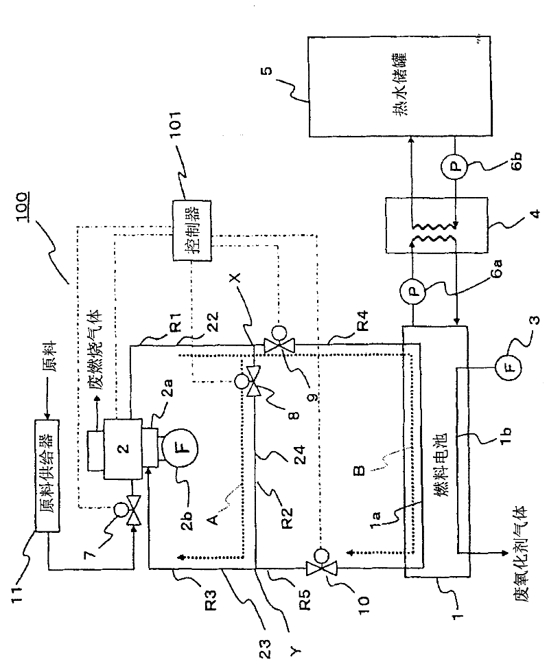
[0079] figure 1 It is a block diagram schematically showing the configuration of the fuel cell system according to Embodiment 1 of the present invention. In addition, in figure 1 In , the solid lines between the respective components constituting the fuel cell system indicate the transmission paths of water, fuel gas, oxidant gas, and electrical signals. In addition, the arrows attached to these solid lines indicate the flow direction in which water, fuel gas, oxidant gas, and the like are conveyed. In addition, in figure 1 In the figure, only components necessary for explaining the present invention are shown, and illustration of other components is omitted.
[0080] First, the configuration of the fuel cell system 100 according to Embodiment 1 will be briefly described below.
[0081] like figure 1 As shown, the fuel cell system 100 of the first embodiment includes: the fuel cell 1 as the main body of the power generation unit, the fuel gas generator 2 for supplying...
Embodiment approach 2
[0166] The fuel cell system in Embodiment 2 related to the present invention will be described below.
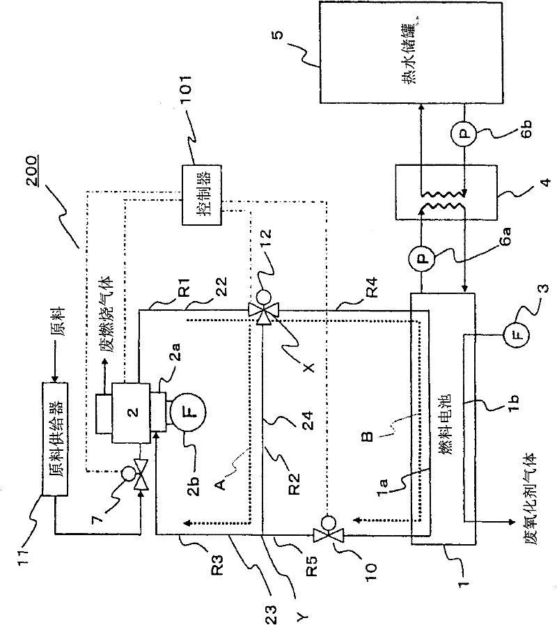
[0167] image 3 It is a block diagram schematically showing the configuration of the fuel cell system 200 according to Embodiment 2 of the present invention. In addition, in image 3 In , the solid lines between the various components constituting the fuel cell system still indicate the paths through which the fuel gas or oxidant gas flows, and the arrows marked on these solid lines indicate the flow of water and fuel gas or oxidant gas. Flow direction during operation. In addition, in image 3 In FIG. 2 , only components necessary for describing the present invention are shown, and illustration of other components is omitted here. In addition, in image 3 In , the same reference numerals are attached to the same components as those of the fuel cell system 100 shown in the first embodiment.
[0168] like image 3 As shown, the basic configuration of the fuel cell syst...
Embodiment approach 3
[0182] The fuel cell system in Embodiment 3 related to the present invention will be described below.
[0183] Figure 5 It is a block diagram schematically showing the configuration of the fuel cell system 300 according to Embodiment 3 of the present invention. In addition, in Figure 5 In , the solid lines between the various components constituting the fuel cell system still indicate the paths through which the fuel gas or oxidant gas flows, and the arrows marked on these solid lines indicate the flow of water and fuel gas or oxidant gas. Flow direction during operation. In addition, in Figure 5 In the figure, only components necessary for explaining the present invention are shown, and illustration of other components is omitted. Additionally, for Figure 5 Components that are the same as the components of the fuel cell system 100 shown in Embodiment 1 are assigned the same reference numerals.
[0184] like Figure 5 As shown, the basic configuration of the fuel ce...
PUM
 Abstract
Description
Claims
Application Information