
Liquid supply device and liquid ejecting apparatus

A technology of liquid supply and injection device, which is applied in printing and other directions, and can solve the problems that the position of the choke valve is not disclosed, and there is no choke valve.

Active Publication Date: 2010-01-27
SEIKO EPSON CORP
View PDF4 Cites 8 Cited by
  • Summary
  • Abstract
  • Description
  • Claims
  • Application Information

AI Technical Summary

Problems solved by technology

[0017] In addition, the ink supply device disclosed in Patent Document 2 does not have a structure for performing slug cleaning, and therefore does not have a slug valve.
For example, in order to properly perform choke cleaning, it is necessary to arrange the choke valve at an appropriate position, but there is no disclosure on the disposition position of such a choke valve.

Method used


Image

  • Liquid supply device and liquid ejecting apparatus
  • Liquid supply device and liquid ejecting apparatus
  • Liquid supply device and liquid ejecting apparatus

Examples


Deformed example 1

[0204] As the choke valve, a non-spring-biased differential pressure valve is used, but a spring-biased differential pressure valve may also be used. In addition, the choke valve may be constituted by a solenoid valve. Even with these configurations, as long as the slug valve is provided on the recording head and the slug cleaning can be completed by one discharge drive of the pump 23, effective slug cleaning can be performed without wasting ink.

Deformed example 2

[0206] The buffer chamber 32 can also be discarded. As long as sufficient ink can be supplied even during suction driving of the pump 23 , there is no problem even if there is no buffer chamber 32 . In addition, in the structure without the buffer chamber 32, it is easier to set the ink outflow amount Vink to be less than the ink ejection amount Ppump that can be supplied by one ejection drive of the pump 23, and one ejection amount of the pump 23 can be obtained. Actuation can end the effect of the barrier wash.

Deformed example 3

[0208] The pump is not limited to a diaphragm pump, and other pulsation type pumps capable of suction drive and discharge drive may be used. For example, bellows type pumps (ripple type pumps) and piston type pumps may also be used. Even in this case, by satisfying the condition of the ink outflow amount Vink<the ink outflow amount Vpump, the gas barrier cleaning can be completed by one discharge drive of the pump, and effective gas barrier cleaning can be performed.


PUM


Abstract

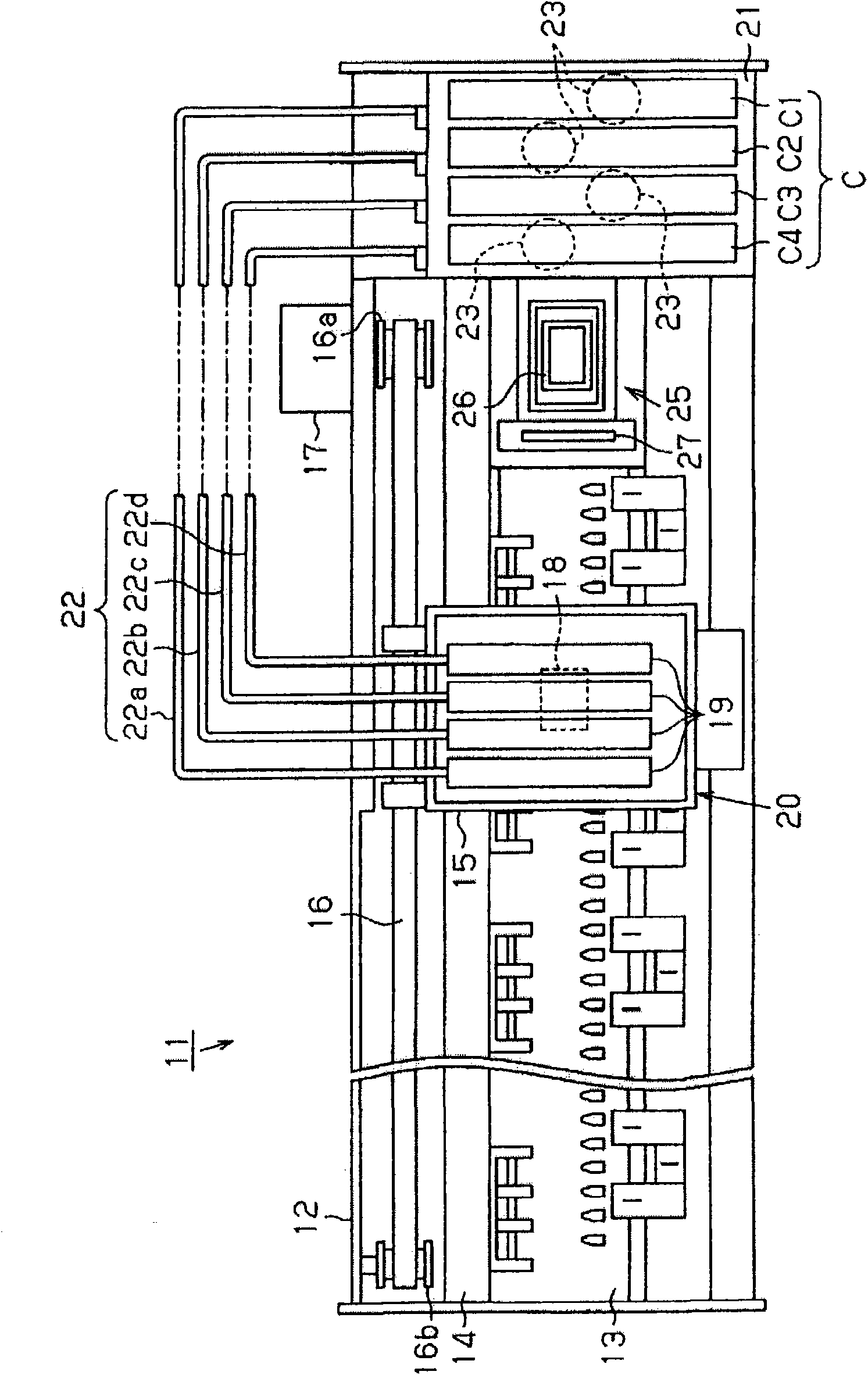
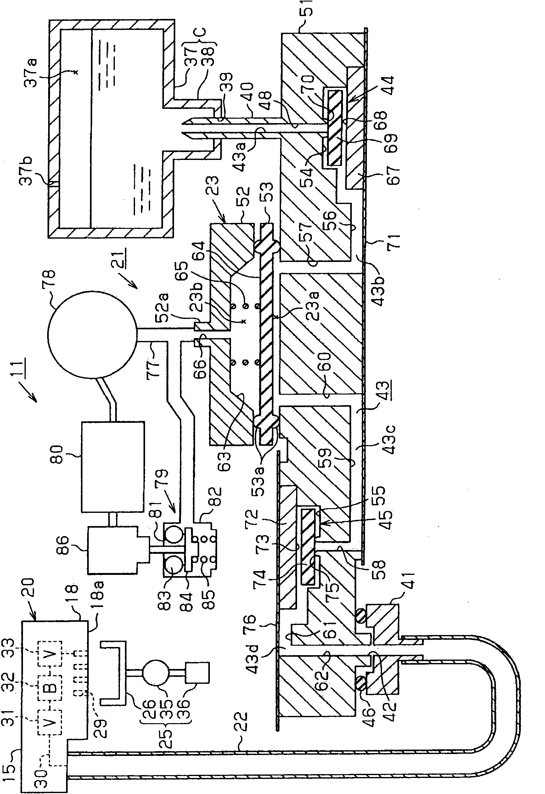
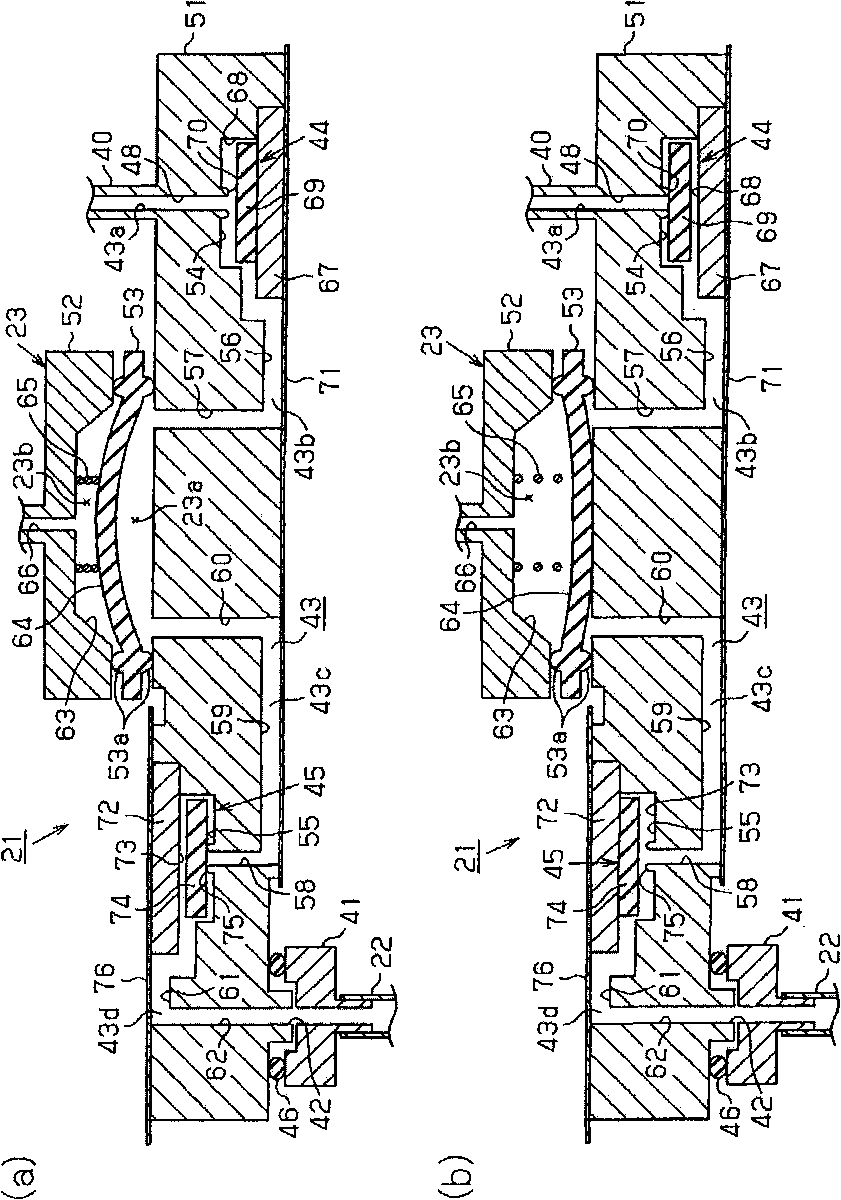
The invention provides a liquid supply device and liquid ejection apparatus, with the capability of securing a relatively high bubble discharge ability at the time of the choke cleaning of the liquid ejecting head, even in a configuration in which the feeding pump type liquid supply section is provided. Enough liquid is supplied to the liquid ejecting head when performing a suction drive of the pump. A printer (11) comprises a liquid supplying device (21), wherein the liquid supplying device (21) comprises a pump (23), an unidirectional valve (44) for suction on upstream side of the pump (23), an unidirectional valve (45) for ejection on downsream side of the pump (23), wherein the liquid supplying device (21) is connected with a recording head unit (20) by a liquid supplying pipe (22). In the recording head unit (20), the middle of the liquid flow channel (30) communicated with a nozzle (29) is provided with a choke valve (31), a buffer chamber (32) and a self-seal valve (33) which are arranged in turn from the downstream side. The liquid volume obtained by the sum of the flow channel volume from the choke valve (31) to the nozzle (29) and the volume of a cover (26) is lower than the liquid amount driven by the pump form one time. In addition, the buffer chamber (32) comprises a liquid storage chamber partly blocked by the film and the film comprises the structure of non-spring force-application type which is not applied with force by the spring.

Description

technical field [0001] The present invention relates to a liquid supply device and a liquid ejection device. The liquid supply device is provided in the liquid ejection device. The liquid ejection device has: a liquid ejection head having an ejection port for ejecting liquid; The ejection port forcibly ejects liquid, and the liquid supply device has a liquid supply mechanism. downstream second check valve. Background technique [0002] Conventionally, in an inkjet printer which is a liquid ejecting device, characters, images, etc. are recorded by ejecting ink droplets as a liquid from a recording head toward a target (paper, etc.). In addition, such a printer is equipped with an ink cartridge (liquid container) as an ink supply source for supplying ink to a recording head. Known ink supply methods for supplying ink from an ink cartridge to a recording head include a method using a head difference based on the ink liquid level of the ink cartridge and the nozzle height of t...

Claims


Application Information

Patent Timeline
IPC IPC(8): B41J2/01B41J2/175B41J2/165B41J2/135
Inventor 高桥优
Owner SEIKO EPSON CORP
Learn More