
Self-lubricating vacuum pressure compound air pump

A vacuum pressure, self-lubricating technology, applied to pumps, pump components, rotary piston pumps, etc., can solve the problems of gas turbulence, unadjustable working plane, slow heat dissipation of compressed gas, etc., to facilitate adjustment and improve trouble-free work Time, the effect of improving product life

Inactive Publication Date: 2010-01-27
杨永坚
View PDF0 Cites 2 Cited by
  • Summary
  • Abstract
  • Description
  • Claims
  • Application Information

AI Technical Summary

Problems solved by technology

[0003] The technical problem to be solved by the present invention is: A self-lubricating vacuum pressure composite air pump has been developed to solve the problems of slow heat dissipation of compressed gas, unadjustable working plane and easy generation of gas turbulence in the existing air pump.

Method used


Image

  • Self-lubricating vacuum pressure compound air pump
  • Self-lubricating vacuum pressure compound air pump
  • Self-lubricating vacuum pressure compound air pump

Examples


Embodiment Construction

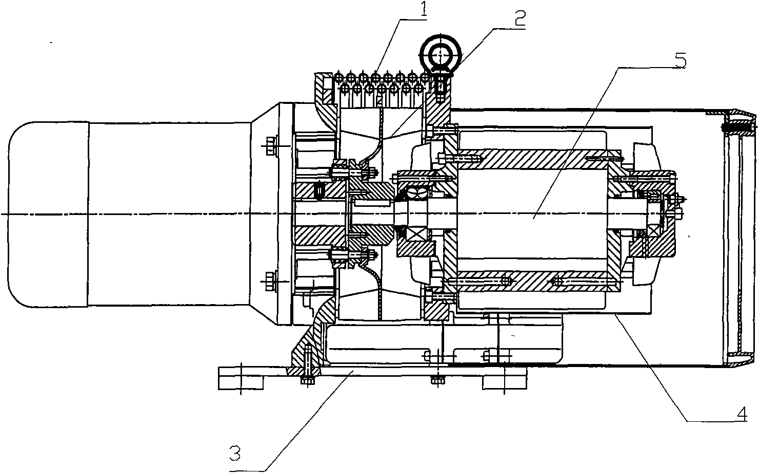
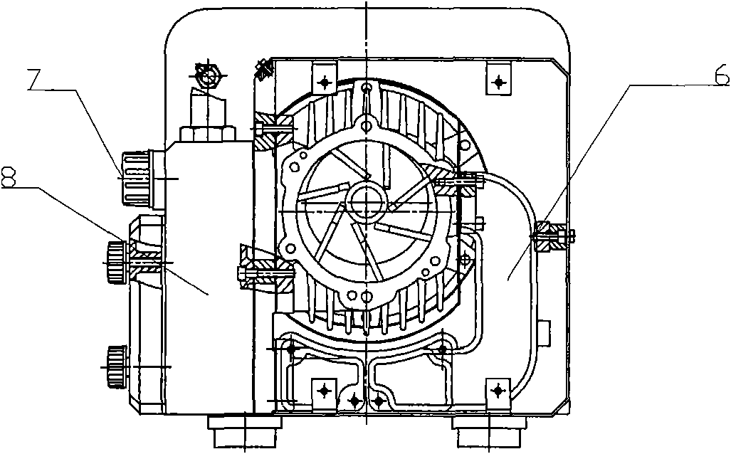
[0014] like figure 1 The one shown is connected with an exhaust elbow on the pump body, and the exhaust elbow is connected to one end of the recooling component. There is an air duct 9 on the top of the exhaust chamber 8, and the air duct 9 is connected to the cooling pipe 1. The cooling component It is installed outside the pump body and covered above the fan. There is a shroud 4 between the pump body and the outer cover, and a bracket is fixed at the bottom of the air pump.

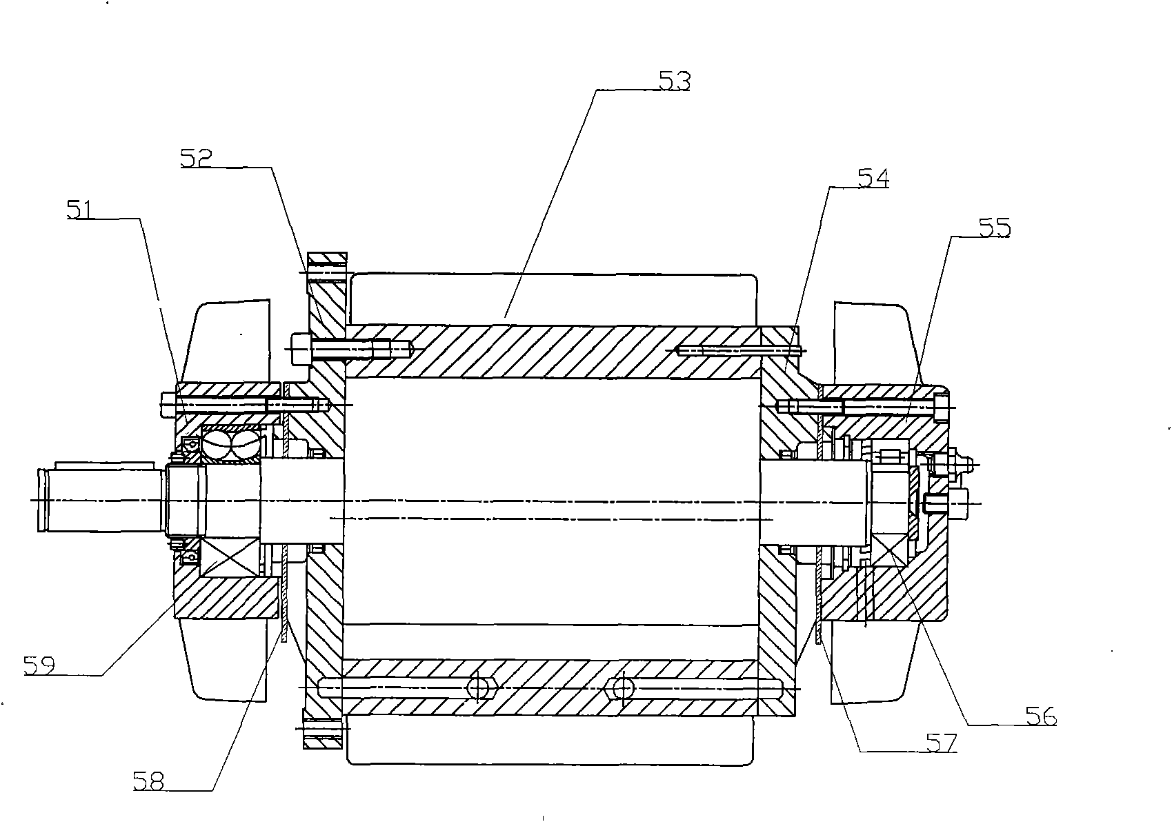
[0015] like image 3 The structure of the pump body 5 shown is that the front end is provided with a front end cover 52, and the rear end of the pump body 7 is provided with a rear end cover 54, and a front bearing seat 51 is installed on the boss of the front end cover 52, which is fixedly connected by screws, and the front bearing Front bearing 59 is installed in the seat 51, and rear bearing seat 55 is installed on the boss of rear end cover 54, and rear bearing 66 is installed in the rear bearing s...


PUM


Abstract

The invention relates to a self-lubricating vacuum pressure compound air pump, which belongs to the technical field of air compressing or delivering machinery for vacuumizing air and outputting compressed air synchronously. The self-lubricating vacuum pressure compound air pump consists of a motor and a pump head, wherein the inside of the pump head is provided with a pump body; a cooling fan is arranged on the pump body near the motor; and a cooling part is arranged at the periphery of the cooling fan of the pump head; a fairing is arranged between the pump body and an outer cover; a bracket is fixed at the bottom of the air pump; the front end of the pump body is provided with a front end cover; the back end of the pump body is provided with a back end cover; a front bearing block is arranged on the front end cover; a back bearing block is arranged on the back end cover; a front bearing is arranged on the front bearing block; a back bearing is arranged on the back bearing block; and a rotating shaft penetrates the front bearing and the back bearing. The self-lubricating vacuum pressure compound air pump solves the problems of slow cooling of the compressed air, unadjustable working plane and easy generation of air turbulence in the prior air pumps.

Description

technical field [0001] The invention relates to the mechanical technical field of simultaneously evacuating air and outputting compressed air for compressing or transporting air, in particular to a self-lubricating vacuum pressure composite air pump. Background technique [0002] Most of the existing air pumps used in conjunction with printing machines are ZYB vacuum pressure composite air pumps. Since this type of air pump rotates at high speed during operation, friction occurs when the sliding vane slides radially in the rotor groove, which generates a large amount of heat. The temperature between the sliding vane and the rotor will soon rise to over 400°C. The overheating of the sliding vane and the rotor will cause the rotor and the sliding vane to be damaged at the same time, and even the motor will be burned. In order to ensure the normal operation of the air pump, an oil lubrication device and cooling are used. However, when the air pump works for a long time, due to ...

Claims


Application Information

Patent Timeline
IPC IPC(8): F04C29/04F04C29/00F04C18/344
Inventor 吴新生杨佳民
Owner 杨永坚
Learn More