Impeller

An impeller and fan blade technology, which is applied to the components of pumping devices for elastic fluids, non-variable volume pumps, machines/engines, etc., can solve the problem of large residual stress, large force on the hub disk and leaf stem, and potential safety hazards. and other problems, to achieve the effect of eliminating hidden safety hazards, small installation size and accurate positioning

Inactive Publication Date: 2010-01-27
JIANGSU FULIHUA GENERAL EQUIP
View PDF0 Cites 13 Cited by
  • Summary
  • Abstract
  • Description
  • Claims
  • Application Information

AI Technical Summary

Problems solved by technology

At present, there are roughly two ways for the hub disc to clamp the petiole. The first is that the installation angle of the petiole in the hub disc can be adjusted. Correspondingly, the shape of the petiole is cylindrical, and a pair of hub discs are used for fixing The installation groove of the petiole is semi-cylindrical, and a pair of hubs fit together to clamp the petiole. In this way, although the installation angle of the petiole can be adjusted, it is difficult to ensure that the installation angles of all fan blades are the same, and the petiole and The fixing of the hub completely depends on the friction force of the contact surface between the two. The tighter the clamp, the greater the friction and the firmer the fixation. However, excessive clamping can easily cause excessive force on the hub and petiole , the residual stress is large, and there are potential safety hazards in long-term operation; the second is that the installation angle of the petiole in the hub cannot be adjusted. Correspondingly, a pair of parallel surfaces are set on the upper and lower sides of the petiole, and the The bottom of the installation groove of the petiole is flat, which can be fixed firmly, but the installation angle of the petiole in the hub cannot be adjusted, that is, the angle of the blade cannot be adjusted, because in various applications, different angles are required blades, which requires production molds corresponding to blades with different angles, which not only increases the production cost, but also adds trouble to management and processing
In addition, under the premise of achieving the same aerodynamic index, the fewer the number of blades, the larger the width of the blades, which will cause the axial height of the fan to be higher, and the blades in the large air volume axial flow fan will be wider, making the fan The axial height is higher, which is not conducive to the miniaturization of equipment using this type of fan

Method used


Image

  • Impeller
  • Impeller
  • Impeller

Examples


Embodiment Construction

[0013] Specific embodiments of the present invention will be described in detail below in conjunction with the accompanying drawings.

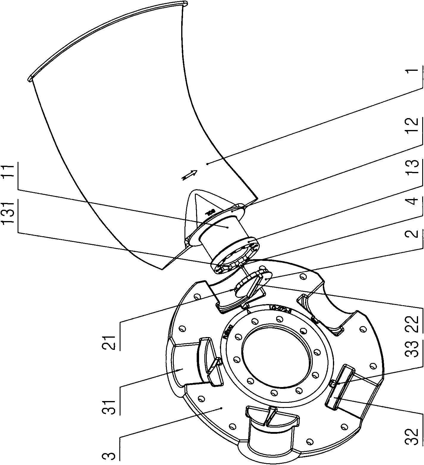
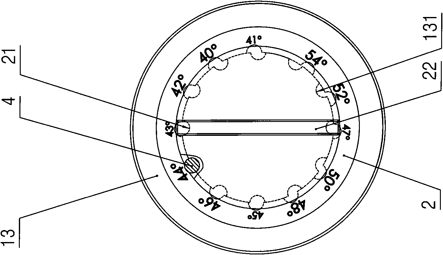
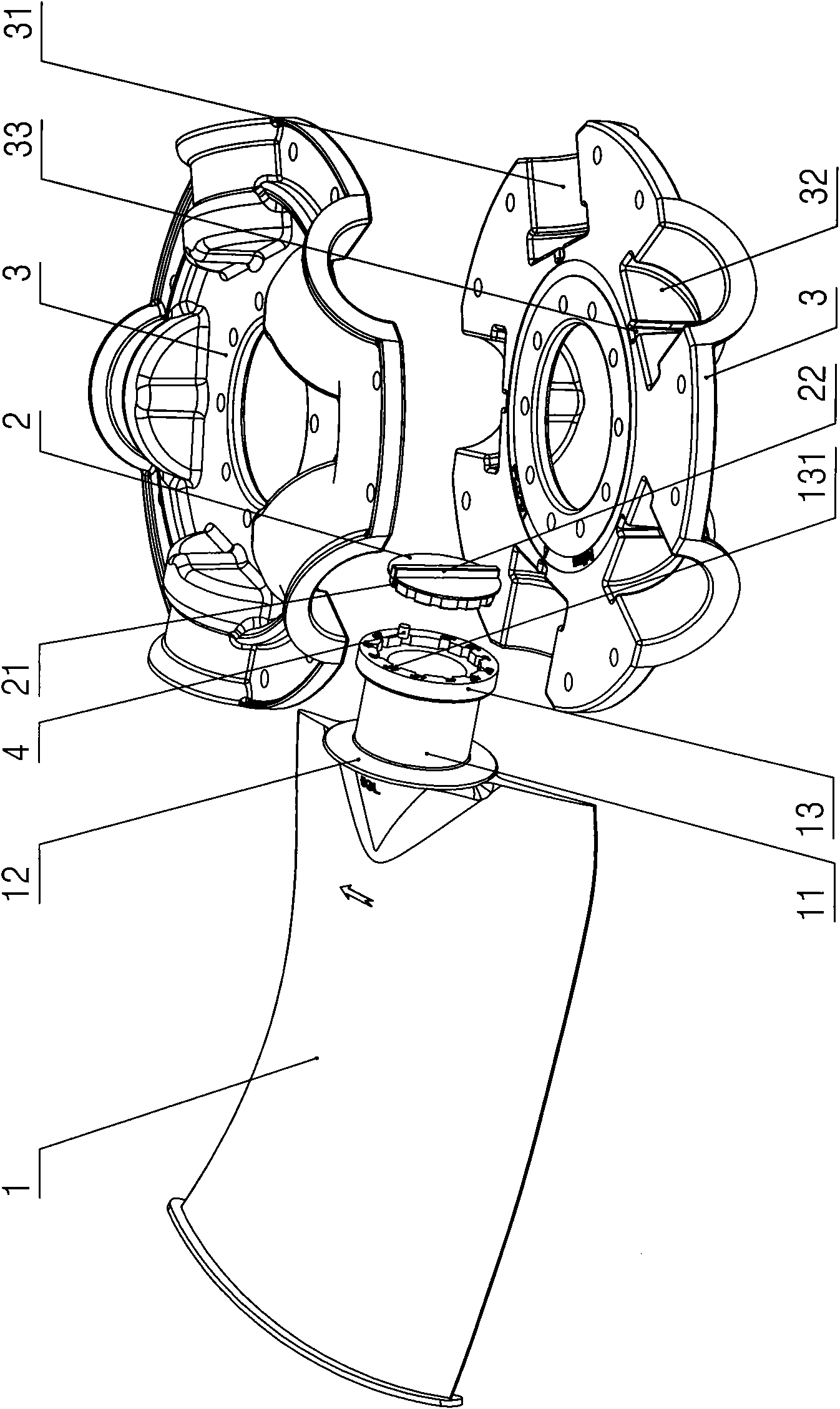
[0014] Such as figure 1 , image 3 As shown, the impeller of the present invention includes: a pair of hub discs 3, five fan blades, five positioning discs 2 and five straight pins 4, each fan blade includes: The petiole at the root, each petiole includes: a cylindrical support arm 11 and positioning edges 12 and positioning seats 13 provided with both sides of the support arm 11, forming a similar I-shaped wheel structure, such as figure 2 As shown, the outer edge of the inner end surface of the positioning disc 2 is provided with twelve equal-diameter inner semi-cylindrical grooves 21, the outer end surface of the positioning disc 2 is provided with a positioning key 22, and the end surface of the positioning seat 13 A placement cavity that matches the positioning disc 2 is provided, and an outer semi-cylindrical groove 131 corresponding ...


PUM


Abstract

The invention discloses an impeller allowing fan blades to be firmly clamped in wheel hub discs at different angles, which comprises a pair of wheel hub discs and at least two fan blades, wherein each fan blade comprises a blade and a blade stem; each blade stem comprises a cylindrical supporting arm, a positioning edge and a positioning seat; the outer edge of the inner end face of each positioning disc is provided with at least two equant inner semi-cylindrical grooves; the outer end faces of the positioning discs are provided with positioning keys; the positioning discs are arranged in accommodating cavities on the end face of the positioning seats; the circumferential walls of the accommodating cavities are provided with outer semi-cylindrical grooves corresponding to the inner semi-cylindrical grooves one by one; one positioning seat and one positioning disc are closed together by cylindrical pins arranged in one pair of inner and outer semi-cylindrical grooves; each wheel hub is provided with front semi-cylindrical grooves which are used for mounting the supporting arms and the same as the fan blades in number and rear semi-cylindrical grooves which are used for mounting the positioning seats and the positioning discs and the same as the fan blades in number; and the rear walls of the rear semi-cylindrical grooves are provided with key slots of the positioning keys. The impeller is mainly used in axial flow fans.

Description

technical field [0001] The invention relates to a fan, in particular to an impeller in the fan. Background technique [0002] As we all know, the impeller usually includes: a pair of hub disks and several blades, each blade includes a blade and a petiole arranged at the root of the blade, and the blade handle of each blade is clamped in the hub disk. At present, there are roughly two ways for the hub disc to clamp the petiole. The first is that the installation angle of the petiole in the hub disc can be adjusted. Correspondingly, the shape of the petiole is cylindrical, and a pair of hub discs are used for fixing The installation groove of the petiole is semi-cylindrical, and a pair of hubs fit together to clamp the petiole. In this way, although the installation angle of the petiole can be adjusted, it is difficult to ensure that the installation angles of all fan blades are the same, and the petiole and The fixing of the hub completely depends on the friction force of th...

Claims


Application Information

Patent Timeline
Patent Type & Authority Applications(China)
IPC IPC(8): F04D29/38F04D29/34
Inventor 沈坤华
Owner JIANGSU FULIHUA GENERAL EQUIP
Why Eureka
Try Eureka