Sunlight collecting device

A technology for collecting devices and sunlight, applied in solar thermal devices, solar collectors, heating devices, etc., can solve problems such as difficult to improve light collection efficiency, additional space required for rotation, and damage to building structures

Inactive Publication Date: 2010-01-27
TSMTECH
View PDF0 Cites 6 Cited by
  • Summary
  • Abstract
  • Description
  • Claims
  • Application Information

AI Technical Summary

Problems solved by technology

[0002] In the past, the traditional light collecting device formed an opening on the top floor of the building and installed a glass cover to allow light to enter the room. In addition to damaging the structure of the building, it is also prone to water leakage and it is not easy to improve the light collection. Efficient and difficult to redistribute sunlight to other floors or rooms in the building
In the traditional technology, it is also mentioned that a sensor ca

Method used


Image

  • Sunlight collecting device
  • Sunlight collecting device
  • Sunlight collecting device

Examples


Embodiment Construction

[0013] In the following embodiments of the present invention, the structure and operating principle of the solar light collection device are mainly described respectively, but these embodiments are only used to illustrate the present invention rather than limit the scope of the present invention.

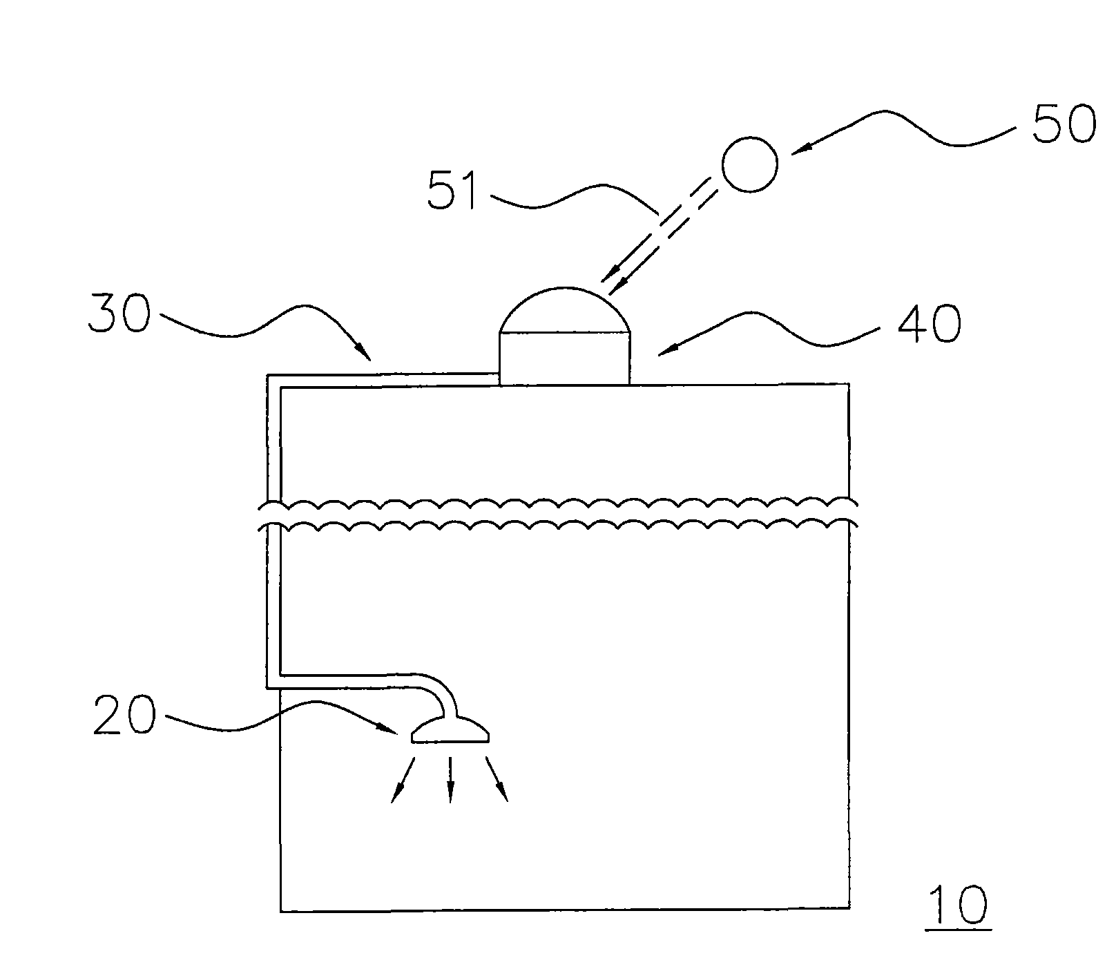
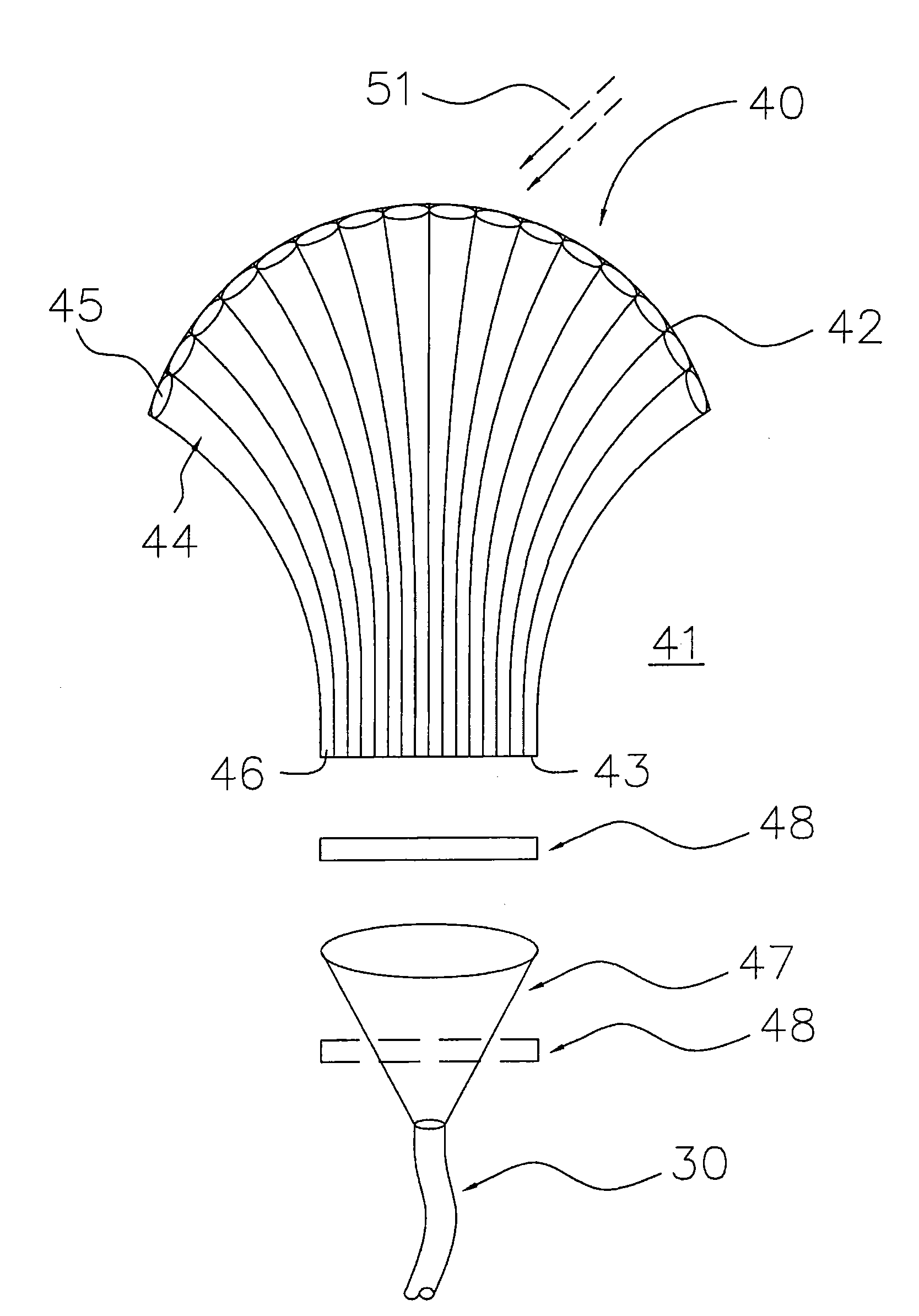
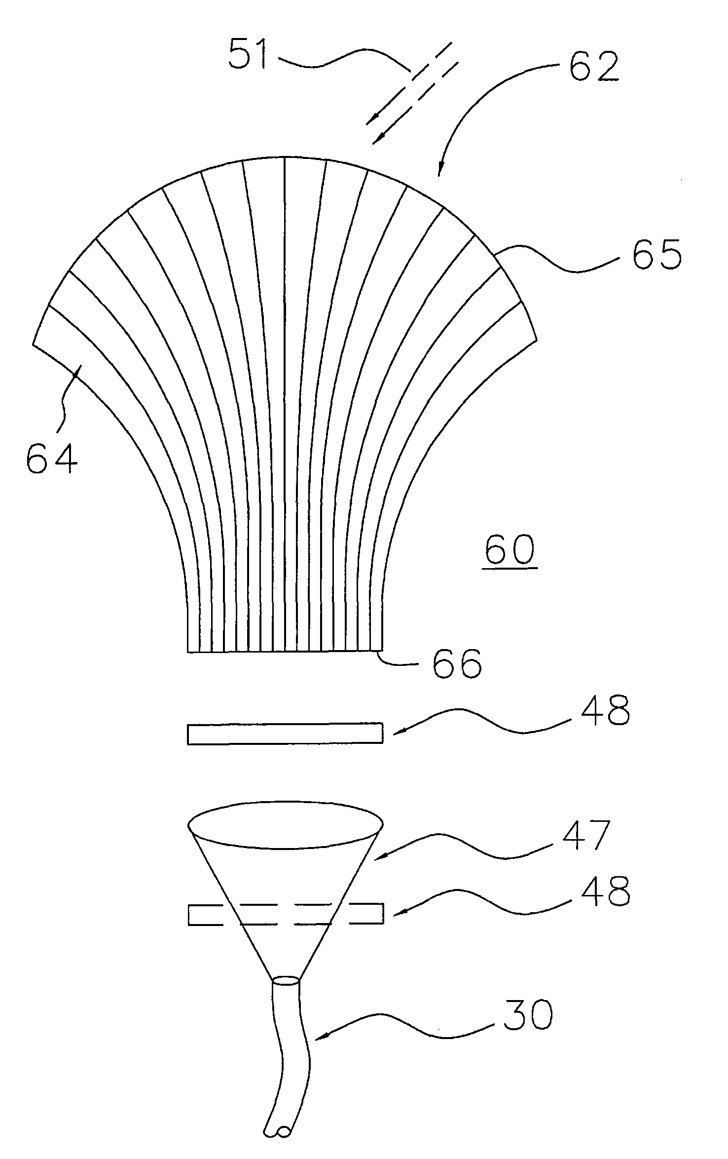
[0014] in figure 1 It shows a solar collection device according to the first preferred embodiment of the present invention, which is installed on a building. figure 2 draw figure 1 An embodiment of a solar collection device. image 3 draw figure 1 Another embodiment of a solar harvesting device.

[0015] Sunlight collection device - fiber optic array

[0016] see figure 1 , the main body 40 of the solar light collecting device is disposed on a building 10, such as a space on the top floor. Meanwhile, a light guiding device 30 is coupled to the main body 40 of the light collecting device, and can enter the room along the side wall of the building. In this way, the light 51 em...


PUM


Abstract

The invention discloses a sunlight collecting device, which comprises an optical fiber array and a light guide device. The optical fiber array comprises a light emitting surface and a light receiving surface that has an arc convex contour, wherein the optical fiber array consists of a plurality of optical fibers each of which is provided with a first end face of a big area and a second end face of a small area; the first end faces are distributed on the arc convex contour of the light receiving surface so as to collect sunlight; and the second end faces are distributed on the light emitting surface. The optical fibers are parallel with one another at a position adjacent to the light emitting surface. The light guide surface is coupled with the light emitting surface of the optical fiber array so as to guide in the collected sunlight.

Description

technical field [0001] The present invention relates to a light collection device, and in particular to a sunlight collection device. Background technique [0002] In the past, the traditional light collecting device formed an opening on the top floor of the building and installed a glass cover to allow light to enter the room. In addition to damaging the structure of the building, it is also prone to water leakage and it is not easy to improve the light collection. Efficient and difficult to redistribute sunlight to other floors or rooms in the building. In the traditional technology, it is also mentioned that a sensor can be installed to detect the operating position of the sunlight, and at the same time, the electromechanical system is used to rotate the light collecting device to align it with the sunlight. However, the sensor is expensive and is easily affected by the ambient temperature. This necessitates a complex cooling design and additional space for rotation, whi...

Claims


Application Information

Patent Timeline
IPC IPC(8): G02B19/00G02B6/00G02B6/32G02B6/34F24J2/08F24S23/30
CPCY02E10/40F24J2/08F24J2/067F24S23/30F24S23/12
Inventor 游朱义
Owner TSMTECH
Why Eureka
Try Eureka