Liquid crystal display

A technology of liquid crystal display and liquid crystal molecules, which is applied in static indicators, instruments, nonlinear optics, etc., can solve the problems of large black state light leakage, low contrast, inability to obtain no color cast and background color, etc., and achieve fast response speed and improved The effect of contrast

Active Publication Date: 2010-01-27
SHANTOU GOWORLD DISPLAY (PLANT II) CO LTD
View PDF0 Cites 9 Cited by
  • Summary
  • Abstract
  • Description
  • Claims
  • Application Information

AI Technical Summary

Problems solved by technology

[0002] There are many working modes for liquid crystal displays, among which super twisted nematic liquid crystal display (Super Twist Nematic Liquid Crystal Display, referred to as STN-LCD) mainly uses the super twisted birefringence effect of liquid crystal molecules to realize the display, this mode has serious problems Dispersion phenomenon, when used as a negative display in a normally black state, it is impossible to obtain a background color withou

Method used


Image

  • Liquid crystal display
  • Liquid crystal display
  • Liquid crystal display

Examples


Embodiment 1

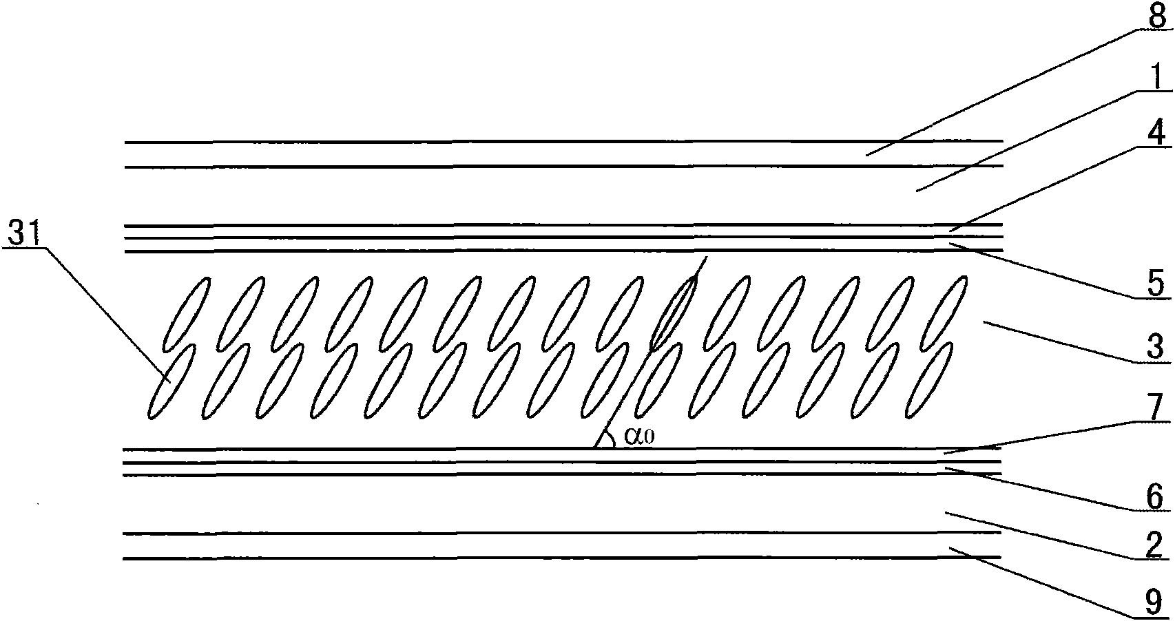
[0036] Such as figure 1 As shown, this liquid crystal display includes an upper transparent substrate 1, a lower transparent substrate 2 and a negative liquid crystal layer 3; an upper electrode 4 is provided on the inner surface of the upper transparent substrate 1, and an upper alignment layer 5 is provided on the inner surface of the upper electrode 4; The inner surface of the lower transparent substrate 2 is provided with a lower electrode 6, and the inner surface of the lower electrode 6 is provided with a lower alignment layer 7; the negative liquid crystal layer 3 is arranged between the upper alignment layer 5 and the lower alignment layer 7; the upper transparent substrate 1 An upper polarizer 8 is arranged on the outer surface, and a lower polarizer 9 is arranged on the outer surface of the lower transparent substrate 2 .

[0037] The aforementioned inner side refers to the side facing the negative liquid crystal layer 3 , and the outer side refers to the side away f...

Embodiment 2

[0049] In this embodiment, on the basis of the liquid crystal display of embodiment 1, a compensation film (not shown) is provided between the upper polarizer 8 and the negative liquid crystal layer 3 or between the lower polarizer 9 and the negative liquid crystal layer 3; The phase delay of the compensation film (that is, the compensation amount) is well matched to the phase delay of the negative liquid crystal layer 3 without an electric field applied. The compensation film can be a positive optical compensation film whose optical axis direction is perpendicular to the alignment direction of the liquid crystal molecules 31, or a negative optical compensation film whose optical axis direction is on a plane determined by the alignment direction of the liquid crystal molecules 31 and the direction perpendicular to the plane of the liquid crystal display. compensation film. In the absence of an electric field, the phase retardation of the compensation film and the phase retarda...

Embodiment 3

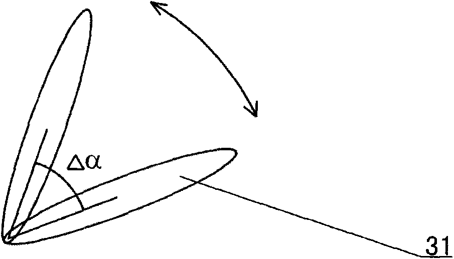
[0052] This embodiment is further improved on the basis of the liquid crystal display of embodiment 1, 2, and the liquid crystal display adopts the following drive mode (this drive mode is called the jitter drive mode, refer to image 3 ): by controlling the periodic change of the driving signal, the inclination angle of the liquid crystal molecules 31 in the negative liquid crystal layer 3 is periodically changed within a certain range (ie Δα), that is, the liquid crystal molecules 31 are within a certain angle range (ie Δα ) oscillates periodically.

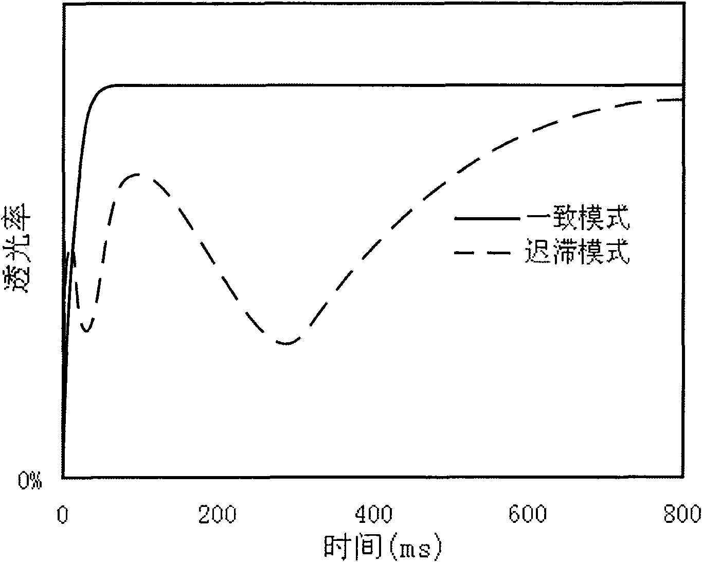
[0053] The periodic oscillation of the liquid crystal molecules 31 will make the angle of the blind area continuously shift, so that the blind area is diffused and weakened, such as Figure 4 As shown, in the vicinity of the blind area of ​​the anti-angle, the light transmittance of the non-jitter driving method is close to zero, while the light transmittance of the jitter driving method can reach about 6%.

[0054] Assuming t...


PUM

PropertyMeasurementUnit
Pretiltaaaaaaaaaa

Abstract

The invention relates to a liquid crystal display which comprises an upper transparent substrate, a lower transparent substrate and a negative liquid crystal layer, wherein the internal side surface of the upper transparent substrate is provided with an upper electrode, and the internal side surface of the upper electrode is provided with an upper alignment layer; the internal side surface of the lower transparent substrate is provided with a lower electrode, and the internal side surface of the lower electrode is provided with a lower alignment layer; the negative liquid crystal layer is arranged between the upper alignment layer and the lower alignment layer; and pretilt angles of liquid crystal molecules in the negative liquid crystal layer range from 70 degrees to 89 degrees. When an electric field is instantaneously added to the liquid crystal display, the tilt directions of all liquid crystal molecules keep consistent, therefore, the liquid crystal molecules are quite stable in the tilting process and high in response speed. A preferable scheme is as follows: the contrast of the liquid crystal display can be improved through the arrangement of compensation membranes. A jitter-driven mode is preferably adopted, thereby dispersing and weakening blind areas. In the preferable scheme, active areas of the liquid crystal display are divided into a plurality of orienting areas, at least two orienting areas of the liquid crystal molecules exist in the active areas, and the orienting directions of the orienting areas are different from each other so that the visual angle uniformity of the liquid crystal display is further improved.

Description

technical field [0001] The invention relates to a liquid crystal display. Background technique [0002] There are many working modes for liquid crystal displays, among which super twisted nematic liquid crystal display (Super Twist Nematic Liquid Crystal Display, referred to as STN-LCD) mainly uses the super twisted birefringence effect of liquid crystal molecules to realize the display, this mode has serious problems Dispersion phenomenon, when used as a negative display in a normally black state, it is impossible to obtain a background color without color cast, and there are disadvantages such as slow response speed and insufficient viewing angle; Twist Nematic Liquid Crystal Display (TwistNematic Liquid Crystal Display, referred to as TN- LCD) mainly uses the optical rotation effect of liquid crystal molecules to realize the display. When this mode is used as a negative display with white characters on a black background, there is a relatively large black state light leak...

Claims


Application Information

Patent Timeline
IPC IPC(8): G02F1/1333G02F1/13363G02F1/133
Inventor 李永忠吕岳敏黄晓炀吴永俊纪伟丰沈奕黄琛
Owner SHANTOU GOWORLD DISPLAY (PLANT II) CO LTD
Why Eureka
Try Eureka