Intelligent video monitoring method and system thereof
An intelligent video surveillance, frame image technology, applied in closed-circuit television systems, image data processing, instruments, etc., can solve the problems of false alarms, images are not emotional enough, poor real-time interactivity, etc., achieve high accuracy, improve alarm accuracy, The effect of improving the response speed
Inactive Publication Date: 2010-01-27
SHENZHEN XINYI TECH CO LTD
1 Cites 95 Cited by
AI-Extracted Technical Summary
Problems solved by technology
[0018] The technical problem to be solved by the present invention is to provide an intelligent video monitoring method and system for the defects ...
View moreMethod used
[0135] The erosion operation in the binary shape transformation is a contraction transformation, which makes the object shrink and the hole is expanded, and the dilation operation is an expansion transformation, which makes the object expand and the hole is shrunk. Therefore, the combination of expansion and erosion can remove noise points on the one hand and fill holes on the other hand. That is, the effect and function of morphological opening and closing operations, and the specific effect is shown in Figure (7-5). Corrosion operation is performed on the input image first, and then expansion operation is performed on the corroded image, so that some small noise points, protrusions and other interferences can be eliminated. At the same time, it can well shrink the holes in the area, which is also the result of the shape opening operation. After the above processing, the noise in the background has been removed, so the extracted moving target is more reasonable.
[0147] The connected regions retained in the binary image are analyzed, the attributes of the target object are judged, and the position of the moving object is precisely positioned. Calculate the center of gravity of the moving object in the image plane, and obtain the coordinates of the center of gravity in the image plane. After obtaining the coordinates of the moving object in the image plane, and mapping it to the real environment, the position of the pedestrian in the real world can be obtained. Use the binary image to locate the upper, lower, left, and right boundaries of the motion area in the horizontal and vertical directions. This method can well locate the range of the motion area.
[0150] As shown in Figure 9, in the Kalman filter position prediction for the moving target, the Kalman filter has many advantages such as simplicity and good real-time performance, and is widely used in engineering. In the target tracking system, especially in the tracking of ground targets in the complex background, the correlation tracking algorithm is a commonly used algorithm. But the problem is that the global search method of the traditional correlation algorithm makes the calculation amount quite large, which is not easy to realize in real time, and when the target is partially occluded, the target is easily lost. In order to solve this problem, this paper adopts a Kalman filter-based target correlation tracking method, making full use of the prediction function of the Kalman filter to predict the area where the target may appear in the next frame, and then performs correla...
View moreAbstract
The invention relates to an intelligent video monitoring method and a system thereof. The system comprises a camera, a first alarm device, a coding processor, a data analyzing processor and a display device. The method comprises the steps of detecting and tracking move targets. The intelligent video monitoring method and the system are executed on the base of common network television monitoring, not only have the advantages of common intelligent video monitoring, but also can bring better income for users. The invention mainly has the following advantages of (1) being capable of reliably monitoring all day long with 24*7; (2) being capable of improving alarm precision due to a strong intelligent characteristic; (3) being capable of improving response speed due to the strong intelligent characteristic; and (4) being capable of effectively enlarging the use of video resources.
Application Domain
Technology Topic
Image
Examples
- Experimental program(1)
Example Embodiment
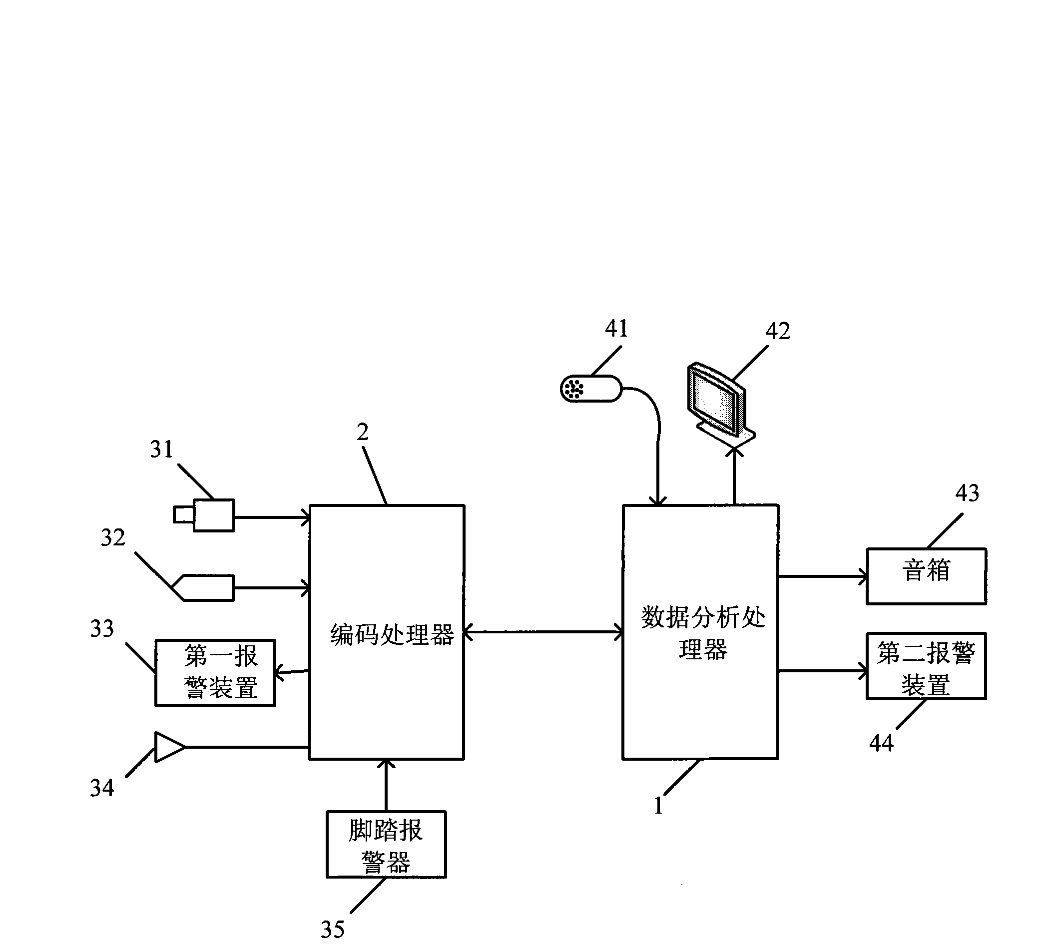
[0066] like figure 1 As shown, in the intelligent video surveillance system of the present invention, comprise camera 31, the first warning device 33, coding processor 2, data analysis processor 1, display 42; Wherein, camera 31 and the first warning device 33 and coding respectively The processor 2 is connected, and the encoding processor 2 and the display 42 are respectively connected with the data analysis processor 1; the encoding processor 2 is used to compress and encode the video stream sent by the camera 31 into a video signal, especially, the encoding processor 2 performs image processing The signal is compressed and encoded by MPEG4, H.263, H.264 or M-JPEG; the data analysis processor 1 is used to send the video signal sent by the encoding processor 2 to the display 42 for display, and analyze and process it. , the code processor 2 sends an alarm signal to the first alarm device 33 for alarming. In addition, the number of the camera 31, the first alarm device 33 and the display 42 can be flexibly configured according to actual needs and user requirements.
[0067] In the specific design, the system adopts the combination of C/S mode and B/S mode. The development environment is: Operating system: Microsoft Windows XP. Database software: Microsoft SQL Server2005, Microsoft Access 2003. Development tools: Microsoft Visual C++2005, Microsoft Asp.Net 2005. Software requirements: DirectX 9.0, DonetFramework 2.0. The hardware environment is CPU: Pentium IV 3.0 or above, RAM 1G or above. Other equipment: video capture camera, digital hard disk video recorder, intelligent tracking high-speed ball, alarm control unit and alarm detector, alarm lights and sirens, on-site display equipment.
[0068] In addition, the camera 31 is implemented as a riot-proof PTZ semi-circular camera, which has the function of PTZ automatic tracking. The comprehensive security site layout overcomes the monitoring blind spot. When there is a target intrusion, the PTZ automatic tracking module can automatically align the target and keep the target within the monitoring range. Inside, when the target hides behind an obstacle, the camera will always be aimed at the obstacle, and relevant personnel can quickly rush to the scene to deal with it. The staff can manually operate the PTZ control lever, or perform automatic monitoring and tracking through the automatic operation module of the software. When the target leaves the monitoring range of a certain camera, other cameras or sensors around it will relay it. As long as the specific target does not leave the entire armed area, the target will always be in the monitoring range. This is different from the previous monitoring mode. When a crime occurs, there is no need for staff to manually operate and track the target. The system can automatically create an alarm event, and automatically track the target, and can quickly display the specific location of the alarm occurrence location. In addition, the encoding processor 2 can be implemented as a video frame capture card, a dedicated device for converting analog video signals into digital video signals. It can receive the analog video signal from the video input terminal, collect and quantize the signal into a digital signal, and then compress and encode it into a digital video. It is the interface between the CCD camera and the computer. The image acquisition system chooses Daheng DHCG300 video acquisition Card, it inherits the characteristics of the PCI image card, that is, the image acquisition and transmission basically does not take up CPU time. data buffer. After trimming, proportional compression and data format conversion, the internal DSP controls graphics coverage and data transmission, and the destination of data transmission is determined by the software, which can be directly transmitted to the computer memory or video memory. It is suitable for image processing, industrial control, multimedia monitoring, office automation and other fields.
[0069] In the serial port communication between the data analysis processor and the peripheral device, when the data is sent out from the serial port, the byte data is converted into serial bits; when the data is received, the serial bits are converted into byte data. In the Windows environment, the serial port is part of the system resources. If the application program wants to use the serial port for communication, it must submit a resource application to the operating system to open the serial port before using it. After the communication is completed, the resource must be released and the serial port must be closed. This system utilizes WindowsAPI function to realize the communication function. The API is an extremely important part of Windows internals. The Windows API is mainly a series of very complex functions and message collections. It can be regarded as an open general function enhancement interface provided by the Windows system for various development systems running under it.
[0070]Data analysis processor 1 is the process of analyzing, processing and applying video images by using computer vision technology, generally including the following four levels: moving target extraction, moving target tracking, target recognition, and behavior analysis; wherein, moving target The purpose of extraction is to effectively eliminate external interference, find and extract moving objects in the screen, in other words, it is a process of forensics, to obtain the evidence we need for video analysis. Because of this, its stability and robustness directly determine the performance of subsequent tracking, identification, and behavior analysis. It can be said that it is the most basic data analysis of data analysis processor 1. From the perspective of technical implementation, it can be divided into three levels: video image change analysis, noise filtering, and region extraction. The change analysis of the video picture is a simple video analysis on the original video stream (compressed or uncompressed), and some regions that have changed relatively over time are obtained. Commonly used algorithms include the difference between adjacent frames or the establishment of a background model, as well as the optical flow method and so on. The purpose of filtering noise is to eliminate the disturbance of light changes and natural and unnatural environmental changes, so how to eliminate the interference of these noises is an important task for effectively extracting moving targets. In general, the causes of noise can be divided into three types. First, camera self-noise, signal interference, and camera shake, such as some small and not very continuous bright spots in the foreground image, basically fall into this category. Second, light changes include indoor and outdoor light changes. Outdoor light changes include weather changes (from cloudy to sunny, sunny to cloudy, and the position of the sun moves), day and night changes, and shadows (clouds, buildings, etc.) change of direction. The noise caused by light changes is often more obvious, and will appear as a large area of false positives in the foreground image. Third, the natural environment interferes. It includes the swaying of leaves, ripples on the water surface, ocean waves, floating clouds, rain, and snow; there are also some unnatural environmental disturbances including flags, banners, fluttering curtains, and reflections on glass walls of buildings, etc. Therefore, compared with the source foreground image, the foreground image after denoising processing will be greatly improved, especially the general shape of pedestrians and cars has become obvious, and the overall noise is much smaller. In the region extraction step, the foreground image processed by the previous two steps is usually in units of pixels, and there is no overall concept of an "object". On the other hand, there are likely to be many gaps in the foreground area processed in this way, which brings inconvenience to describe the shape of the object. In this link, the main purpose of region extraction is to use some basic binary image (black and white) processing algorithms to process the obtained foreground image, fill in the gaps, and distinguish the connected regions, and finally as a whole , its content can include key feature description information such as area size, location, shape, color, pattern, etc., for targeted analysis in the next step. After this step most of the voids contained in the object will be added, and the overall shape of the object will become smoother.
[0071] Then, the tracking of the target is the prerequisite for any intelligent video analysis function (cross-border, intrusion, legacy, theft, wandering, traffic statistics, etc.), because we must know which object, when and where It has appeared, how long it has appeared, the direction of movement, and other information, and these can only be obtained through tracking. A series of static descriptions related to the appearance of the moving target are obtained through region extraction, such as shape, color and so on. However, to track targets and understand their motion information, these descriptions must be used to establish a motion model, that is, to represent the target. There are many ways to build a motion model, depending on different needs. The simplest one can be the center point or centroid point of the target. Its advantage is that the periodicity of the target motion can be clearly observed. In addition, the circumscribed graphics (rectangle, ellipse, etc.) of the target edge can be used to simply describe the shape, size and position of the target object, which can be decomposed into many connected rectangles, so that the movement of the limbs can be well described. Used to analyze the behavior of individuals. Specifically, the extraction and tracking of moving targets are actually two mutually beneficial processes. On the one hand, if the extraction is done very accurately, the tracking will become very simple, as long as the center of the target is selected; Emphasis is placed on the extraction, so that the results obtained will be more accurate. However, precisely because there is so much uncertainty in this regard, we need to weigh the best of both sides. Of course, a stable tracking algorithm is the prerequisite for the best performance. There are many tracking algorithms, some are based on the color position of the object, some are based on the direction of the object's movement, some are cascaded to other objects to assist tracking, and some use templates and so on. But all in all, there is only one purpose, and that is to infer its possible next position based on the previous state of motion (including speed, acceleration, direction, etc.) of the moving object. Then correct and compensate through the moving area information extracted earlier, and then confirm the final position and update the motion state of the object for processing at the next point in time.
[0072] The above are some simple cases of tracking, which often only involve the tracking of one or several independent targets. However, the reality is much more complicated. This includes occlusion, disappearance, and reappearance of single objects, as well as aggregation and separation of multiple objects, etc. We not only need to achieve stable tracking of individuals, but also need to make judgments about these complex situations, so as to take corresponding measures to ensure that there will be no confusion, omissions, repetitions and other errors. The main premise of the video surveillance mentioned above is a single still camera. In addition, applying video analysis technology to multiple or PTZ cameras is also a very popular direction. Among them, the autonomous PTZ tracking can realize the autonomous focusing, moving and stretching of the target of interest without the assistance of other cameras. The algorithm used is very similar to the one we introduced earlier, except that the PTZ parameters need to be adjusted additionally and the delay required for the movement of the PTZ motor to be considered. In addition, there are relay tracking of multiple cameras and master-slave camera tracking, etc., which will not be repeated here.
[0073] The identification of moving targets is an important process, which can not only enhance the stability of the system, reduce the false alarm rate, improve efficiency, but also lay the foundation for the next step of behavior analysis. Recognition includes two processes, one is the process of machine learning, and the other is the process of identifying new targets based on the learned results. Machine learning includes training and testing. Training is the use of known information to guide the machine so that it has the ability to distinguish objects. The test is to test the learned machine with known results, evaluate its performance and re-learn after adjusting if necessary. For example, for the recognition (classification) of cars and people, first we need the sample sets of cars and people, and separate the training set and test set from the samples for training and testing respectively. There are many methods of machine learning, including neural network, support vector machine, data classification (linear and nonlinear), probability (Bayesian, Bayesian network, Markov model, CRF, graphical model, etc.). The basis for classification can be the shape, size, color, pattern, and symmetry of the target object, or the direction, speed, acceleration, rigidity, and periodicity of the target object. The learned machine will construct the corresponding model, template, distribution or subspace for identification.
[0074] During the recognition process, given a new object, the system compares it with the established model and selects the closest match as its label (person, car, etc.). Or it can be mapped to the learned space or distribution, and the category with the highest probability or the closest distance can be selected as the label. The purpose of behavior analysis is to use the recognition results to make targeted behavior judgments for different targets (people, cars, etc.). It implements different functions through different rules according to the appearance time, direction, position, speed, size, distance and relative direction of one or more targets. The basic functions that can be realized include cross-border, latent, speeding, lost, left behind, stranded, etc.; advanced functions include traffic statistics, individual human behaviors such as falling, bending over, and sitting down; and some people and other people or objects interaction, such as handing over items, traffic accidents, getting on and off the car, etc. Behavioral analysis does not have a fixed implementation model. Simple can be a rule, such as speed limit, direction limit, complex can be a model, such as human body model, multi-person interaction model.
[0075] The above system structure has realized that the monitoring room analyzes and processes the video transmitted from the monitoring site. On the one hand, the video image of the monitoring site can be displayed through the monitor 42, and then judged by relevant personnel; Judgment after analysis; then if the relevant personnel or the data analysis processor 1 judges that there is an abnormal situation, a control signal can be sent to the first alarm device 33 on the monitoring site to start the alarm.
[0076] In addition, in order to further enhance the function of this system, peripheral equipment can also be expanded according to actual needs or user requirements. For example, the intelligent video surveillance system also includes: a pickup 32 and a sound box 43, wherein the pickup 32 is connected with the encoding processor 2, and the sound box 43 is connected with the data analysis processor 1; The encoding processor 2 is also used to compress and encode the audio stream sent by the pickup 32 into an audio signal; the data analysis processor 1 is also used to send the audio signal sent by the pickup 32 to the sound box 43 for further processing. play. In this configuration, not only the on-site video can be collected and analyzed, but also the audio can be collected and analyzed, thus avoiding the situation that the camera does not capture the video image but actually an accident occurs, thus further improving the system.
[0077] In another embodiment, the intelligent video surveillance system also includes: a pedal alarm 35 and a second alarm device 44; wherein the pedal alarm 35 is connected with the coding processor 2, and the second alarm device 44 is connected with the data analysis processor 1 connection; the data analysis processor 1 is also used to receive the alarm signal sent by the foot alarm 35 through the encoding processor 2, and control the second alarm device 44 to issue an alarm. In the case of this configuration, it is further enhanced that the monitoring site will actively send an alarm to the monitoring room when an abnormal situation occurs, thereby further enhancing the intelligent performance of the system.
[0078] In a further embodiment, the intelligent video surveillance system also includes: a microphone 41 and a loudspeaker 34; wherein, the microphone 41 is connected with the data analysis processor 1; the loudspeaker 34 is connected with the encoding processor 2; the microphone 41 passes through the data analysis processor 1 And the encoding processor 2 sends the collected audio stream to the speaker 34 for playback. In this embodiment, if the relevant personnel in the monitoring room find a particularly urgent situation, they can remind the personnel on the monitoring site through the microphone to take relevant measures, thereby avoiding accidents.
[0079] In addition, for the setting of various accessories in the system, the first alarm device 33 and the second alarm device 44 are buzzers, multi-tone alarms, or sound and light alarms. The camera 31 includes: at least one lens, and an image sensor, and the image sensor is a CCD image sensor or a CMOS image sensor. The encoding processor 2 performs MPEG4, H.263, H.264 or M-JPEG compression encoding on the image signal.
[0080] In the intelligent video monitoring method of the present invention, it mainly includes two steps: the detection of the moving target and the tracking of the moving target, wherein the detection of the moving target includes: S11: collecting and preprocessing M frame image sequences, wherein M is a natural number; S12: Initialize the background model according to the M frame image sequence; S13: Collect the M+1th frame image sequence, and perform inter-frame difference and background difference processing on the M+1th frame image sequence based on the background model, A moving target is detected; in addition, tracking the moving target includes: S21: establishing a target model for the detected moving target; S22: performing continuous K-frame processing on the detected moving target according to the target model, and establishing a target tracking information table , where K is a natural number; S23: Establish the target matching matrix between two adjacent frames, the matrix elements are the matching degree of the target model between two adjacent frames, and obtain the matching situation of the moving target; S24: According to the target model and the target matching matrix , analyze the state of the moving target in the current frame, and update the target model.
[0081] like figure 2As shown, in the implementation process of the entire monitoring method, it can be divided into three major parts, namely acquisition, detection and tracking; among them, the image sequence is captured by a high-resolution CCD camera, and the video image signal is converted into a digital image by using a video acquisition card sequence and input into Data Analysis Processor 1. Then, the background is extracted through the first M frames of the video stream, and after the differential binarization operation between the current frame and the background, the segmentation result of the target is post-processed by morphological filtering to eliminate the influence of noise and background disturbance. Finally, the connected region detection is carried out to accurately calibrate the moving target. Then, extract the center position and area size information of the moving area, establish the target linked list, and then use Kalman filter to predict the position of the tracked target area motion trend in the target linked list, and carry out the matching search of the target area within the range of the predicted position to establish The association relationship of the target, and the Kalman filter is updated in real time with the best matching motion region.
[0082] like Figure 4-8 As shown, when initializing the background model, comparing adjacent frame images, it will be found that the background pixels change slowly with time, and there is little difference in a certain period of time. However, the pixel points corresponding to the object motion change area change greatly. Therefore, each pixel of the selected background frame can be modeled using a Gaussian model. Here we convert the RGB mode to the HSV color mode, use V=(R+G+B)/3 as the mean value, and the variance is 0 in the first frame, and then calculate different values according to the change of light.
[0083] In the process of image preprocessing, when performing grayscale processing, the GRB components of the image take equal values, and the image is reduced from the original three-dimensional features to the one-dimensional features after grayscale, and some information will inevitably be lost. The common grayscale methods are: Maximum value method, average value method, weighted average method, etc. It can be seen that no matter which method is adopted, its original color features are often changed or lost, so that the same binarization method often obtains different results due to different grayscale processing processes of a color image.
[0084] Considering the rationality of the image, the following formula is selected for grayscale conversion:
[0085] Gray=0.30×R+0.59×G+0.11×B
[0086] R=G=B=Gray
[0087] Among them, Gray represents the gray value of the pixel in the image, R represents the red component of the pixel, G represents the green component, and B represents the blue component. weight.
[0088] When performing image binarization processing, the image is simply divided into background and target object. The most commonly used method is to select a threshold ξ, and use ξ to divide the image into two parts, larger than ξ area (usually the target object) and smaller than ξ area (usually the background), if the input image is f(x, y) and the output image is g(x, y), then
[0089] g ( x , y ) = 1 , f ( x , y ) ≥ θ 0 , f ( x , y ) θ
[0090] When performing image filtering and denoising processing, the input image is filtered to remove noise, image enhancement, and sharpening. Video images are generally preprocessed to improve the visualization of the region of interest, which is conducive to further work on the image. There are mainly mean filtering, median filtering, morphological filtering and so on.
[0091] In the detection process of the changed area, the inter-frame difference can detect the changed area between two adjacent frames. This field actually includes the area covered by the moving object in the previous frame, that is, the revealed area, and the area covered by the moving object now, that is, in the current frame, is the moving object itself.
[0092] The two frames of images are differentially processed. The amount of difference can be grayscale, brightness, chrominance value or other parameters. We use grayscale value for difference. First, set a threshold. If the gray value of the current frame minus the gray value of the next frame is less than this threshold, it is the background, otherwise, it is the foreground. This threshold includes two parts, one part is the grayscale threshold, and the other part represents the change of light, which is the average value of the grayscale value of all pixels. Using the average value of this grayscale, the differential threshold can adapt to the change of light. If the moving object stops in the scene, the position of the object does not change in two adjacent frames, so it is detected as a point in the background in the difference processing. It will not enter the subsequent processing, and it will not be falsely detected as a moving object. Since the changing area needs to be further processed with the background frame to segment the moving object, the selection of the threshold here does not need to be precise, and the adaptability range is very wide.
[0093] Image movement means image change. One of the basic basis of the moving target detection algorithm is the change of image intensity. The difference of a pair of images at adjacent times in the image sequence can be used to represent the relative change of intensity. The image difference operation is defined as
[0094] f d (p,t 1 , t 2 ) = f(p,t 2 )-f(p,t 1 )
[0095] where f d is the difference image, p=(x,y). The operation of the above formula involves the subtraction operation of the corresponding pixel intensity, so this algorithm is quite simple and suitable for parallel implementation. The image difference reflects the higher-level nature of the scene or the image plane Changes in sensor motion. If there are several relatively independent moving objects and a moving sensor in the scene, the differential image is a combination of these movements. The analysis of the difference image can draw the following conclusions:
[0096] (1) Image difference can be used as an approximation for time derivation of image functions. A simple two-point finite difference is the time interval t 2 -t 1 at the middle point of a kind of approximation.
[0097] (2) The difference image has the property of edge image, this is because the image difference algorithm and the image gradient function operator have similar properties.
[0098] (3) In the actual image, the difference image, like the still edge image, is not composed of ideal closed contour areas, but often represents incomplete change information. For example, useful differential image information cannot be obtained when an object is moving in a background with similar intensity (or texture) to its image plane. The information carried by the differential image is not exactly the absolute image intensity change, it is related to the type of change.
[0099] The difference image reflects the change of the image intensity of the two frames before and after, and can also simply estimate the direction of motion. However, the difference image also has the following limitations; first, the difference images of the two frames before and after can only reflect the relative position changes of the moving objects in the two frames of images; second, it also ignores slow moving targets and small moving objects .
[0100] During the detection process of the moving target, the pixels in the segmented motion change area are fitted with their respective Gaussian models. We use the gray level of the pixel to measure the characteristics of this point. If the gray level is less than a specific threshold, it is judged to be a revealed area, otherwise it is a moving object.
[0101] Suppose the video sequence under study is {f k (x, y)} k-1 n (K is the frame sequence, N is the total number of frames of the video sequence), record
[0102] f k (x, y) = b k1k+1 (x,y)+a(x,y)+u k (x,y)+n k (x,y)
[0103] f k+1 (x, y) = b k1k+1 (x,y)+a(x+Δx,y+Δy)+v k+1 (x,y)
[0104] where b k1k+1 (x, y) represents the common background area between the kth and k+1 frames, a(x, y), a(x+Δx, y+Δy) correspond to the moving objects in the K, K+1 frames respectively Area, (Δx, Δy) represents the displacement loss of the moving target from the Kth frame to the K+1th frame, u k (x, y), v k+1 (x, y) respectively represent the covered and exposed background areas caused by the moving target in the K and K+1th frames, n k (x, y), n k+1 (x, y) denote the noise in the Kth and K+1th frames, respectively.
[0105] difference image between adjacent frames
[0106] D(x,y)=f k+1 (x,y)-f k (x,y)
[0107] =[a(x+Δx,y+Δy)-a(x,y)]+v k+1 (x,y)-v k (x,y)
[0108] +n k+1 (x,y)-n k (x,y)
[0109] In the above formula, a(x+Δx, y+Δy)-a(x, y), v k+1 (x, y) and v k (x, y) all belong to the motion change area. Let MR(x, y)=[a(x+Δx, y+Δy)-a(x, y)]+v k+1 (x,y)-v k (x, y) represents the motion change area, n(x, y)=+n k+1 (x,y)-n k (x, y) represents the relative noise between two adjacent frames, then we can get
[0110] D(x,y)=MR(x,y)+n(x,y)
[0111] It can be seen from the above formula that the difference image includes two parts: the motion change area caused by the moving target and the noise, and the motion change area includes the real moving target area, the covered and exposed background area, in order to accurately detect the moving target , especially when the moving speed of the target is fast and the motion displacement between adjacent frames is large, resulting in a large covered and exposed background area in the motion change area, the boundary information of the moving target can be considered. The boundary of the moving object can be obtained by combining the edge detection result of the current frame and the motion change area. Finally, the moving target is detected according to the moving target area obtained by filling the moving target boundary.
[0112] In the process of updating the background, different update frequencies are used to update the exposed area and the background area. Of course, the update frequency of the exposed area is higher than that of the background area. Because the revealed area is the area covered by the moving object in the previous frame and is re-displayed in the current frame, it needs to be updated faster. This processing strategy makes it possible to quickly obtain a clean background frame model as the moving object moves even if there is a moving object during modeling.
[0113] In order to reflect the impact of illumination changes, noise and other factors on the actual background, the background update operation can be performed periodically, and this algorithm can be used for background update. Set I cb is the background image currently saved in the system, I c1 For the image currently collected by the system, calculate the difference image I between the two di , I di =|I ci -I cb |, Adaptive Computing I di Threshold T of T, it is binarized to get I mark :
[0114] I mark ( x , y ) = 1 , I di ( x , y ) ≥ T , 0 , I di ( x , y ) T .
[0115] with I mark For the switch function, construct the instant background I b :
[0116] I b ( x , y ) = I cb ( x , y ) , I mask ( x , y ) = 1 , I cn ( x , y ) , I mask ( x , y ) = 0 .
[0117] Then update the background image as follows:
[0118] I cb (x, y) = a*I b (x,y)+(I-a)*I cb (x, y).
[0119] Among them, a is the weighting coefficient.
[0120] In the noise removal process, due to the various forms of noise: isolated noise points, noise with a small area, noise inside the motion area, etc. For isolated noise points and small-area noise, morphological erosion and expansion can be used to remove them, but for the noise inside the moving area of some moving objects and noise blocks with a certain area, the effect of morphological erosion and morphological expansion is not ideal. The noise processing mainly adopts the edge-passing area labeling method, and counts the number of all connected bodies on the binary map through the edge-passing area marking method, and counts the area, length and width of each connected body. Based on these statistical properties, noisy blocks are filtered out and some holes that may appear in the vehicle are filled.
[0121] Binary morphological expansion and erosion are the most basic binary morphological transformation operations, from which other complex morphological transformations can be formed, such as morphological opening operations, morphological closing operations, skeleton extraction, thinning and other operations. Morphological eclipse, dilation, opening and closing operations are used in preprocessing, so only these basic morphological operations are introduced.
[0122] The translation distance X of a set A can be expressed as A+X, which is defined as:
[0123] A+x={a+x; a∈A}
[0124] Geometrically, as shown in Figure (7-2), A+X means that A has translated a certain distance along the vector X.
[0125] Define B as a binary image and S as a given structural element. From this, the basic binary morphological transformation is obtained. Binary Morphological Corrosion:
[0126] BθS=∩{B-s, s∈S}
[0127] Corrosion can be obtained by translating the input image by -S, and computing the intersection of all translations, where structural elements are defined as flat structures.
[0128] Binary Morphological Expansion:
[0129] B ⊕ S = ∪ { B + s ; s ∈ S } - - - ( 7 - 12 )
[0130] Dilation can be obtained by translating the input image with respect to all points of the structuring element, which is defined as a disk structure, and then computing their union.
[0131] Binary form on:
[0132] BoS = ( BΘS ) ⊕ S - - - ( 7 - 13 )
[0133] Binary form closed:
[0134] BoS = ( B ⊕ S ) ΘS - - - ( 7 - 14 )
[0135] The erosion operation in the binary shape transformation is a contraction transformation, which makes the object shrink and the hole is expanded, and the dilation operation is an expansion transformation, which makes the object expand and the hole is contracted. Therefore, the combination of expansion and erosion can remove noise points on the one hand and fill holes on the other hand. That is, the effect and function of morphological opening and closing operations, and the specific effect is shown in Figure (7-5). Corrosion operation is performed on the input image first, and then expansion operation is performed on the corroded image, so that some small noise points, protrusions and other interferences can be eliminated. At the same time, it can well shrink the holes in the area, which is also the result of the shape opening operation. After the above processing, the noise in the background has been removed, so the extracted moving target is more reasonable.
[0136] In the case of strong light, the detected moving object will contain its shadow, and the shadow needs to be removed when the accuracy of moving object segmentation is high.
[0137] In the process of obtaining the motion area, this system adopts the inter-class variance method of the genetic optimization threshold, and the steps are as follows:
[0138] 1. Parameter encoding: Since the genetic algorithm cannot directly process the solution data of the understanding space, they must be expressed as genotype string structure data of the genetic space through encoding. The parameter encoding usually adopts two forms of binary encoding and real number encoding. Since the gray value of the image is between 0-255, an 8-bit binary code 00000000-11111111 can be used to represent the sub-threshold, and the candidate threshold is between 0-255.
[0139] 2. Population initialization: randomly generate 20 individuals between 0-255, and encode them in binary form as the initial population of the genetic algorithm.
[0140] 3. Population fitness function: define the population fitness function as:
[0141] f = α 1 ( u 1 - u ) 2 + ∂ 2 ( u 2 - u ) 2
[0142] The optimal threshold T of the differential image is the T that maximizes the adaptive function value * , use him to divide the current frame difference image into two parts, the foreground and the background.
[0143] 4. Selection operation: The selection operation is a genetic algorithm used to determine how to select which individuals from the parent population are inherited to the next generation population by a certain method. The purpose of the operation is to avoid gene deletion, improve global convergence and calculation efficiency. Proportional selection is achieved by steamship gambling.
[0144] 5. Crossover operation: First, a pair of individuals to be paired is randomly selected from the individuals in the group estimation, and the crossover position is randomly selected for the individuals to be paired according to the length of the bit string, and the crossover operation is performed according to the crossover probability. Chromosomes exchange some of their genes with each other at the crossover position in a single-point crossover, thus forming two new individuals.
[0145] 6. Mutation operation: Mutation is to randomly change some bits on the chromosome string with a small probability. The mutation probability here is 0.01, and there are two cases for binary string gene mutation: 01, 10.
[0146] 7. End condition: when the number of genetic algebra reaches 60, the determination of the dynamic threshold based on the genetic algorithm of the difference image of the current frame ends, and the obtained threshold is used as the optimal threshold to binarize the difference image.
[0147] Analyze the connected regions retained in the binary image, judge the attributes of the target object, and accurately locate the position of the moving object. Calculate the center of gravity of the moving object in the image plane, and obtain the coordinates of the center of gravity in the image plane. After obtaining the coordinates of the moving object in the image plane, and mapping it to the real environment, the position of the pedestrian in the real world can be obtained. Use the binary image to locate the upper, lower, left, and right boundaries of the motion area in the horizontal and vertical directions. This method can well locate the range of the motion area.
[0148] In the process of target feature extraction, in the process of recognition and tracking, in order to effectively identify and track, accurately determining the target features is the key to motion tracking and matching, and the quality of the extracted target features directly affects the accuracy and speed of target recognition. The main features of the target include: the boundary of the target, which includes four boundaries of up, down, left, and right, which are determined by the projection of the target on the X-axis and Y-axis; the area of the target, which is the number of pixels surrounded by the target boundary; the center of gravity of the target Feature, which is the position of the moving target in the current frame; the main axis of inertia of the target, whose direction is used to describe the extension direction of the target.
[0149] During the establishment of the target model, according to the target features extracted from the binary image, a corresponding feature template is established for the detected moving target. In two adjacent frames of images of the same moving target, the characteristics of the moving position, shape, area, etc. do not change much. Using these features, feature templates can be built for detected objects.
[0150] like Figure 9 As shown, in the Kalman filter position prediction for moving targets, the Kalman filter has many advantages such as simplicity and good real-time performance, and is widely used in engineering. In the target tracking system, especially in the tracking of ground targets in the complex background, the correlation tracking algorithm is a commonly used algorithm. But the problem is that the global search method of the traditional correlation algorithm makes the calculation amount quite large, which is not easy to realize in real time, and when the target is partially occluded, the target is easily lost. In order to solve this problem, this paper adopts a Kalman filter-based target correlation tracking method, making full use of the prediction function of the Kalman filter to predict the area where the target may appear in the next frame, and then performs correlation matching in a smaller prediction area Calculate and find the best relevant matching point, and the target related tracking is more active.
[0151] Among them, the filter principle is that the Kalman filter is an algorithm for linear minimum variance error estimation of the state sequence of a dynamic system, and the system is described by a dynamic state agenda and an observation agenda. It can be observed at any point as the starting point, and calculated by recursive filtering.
[0152] Let the state agenda and observation agenda of the linear system be:
[0153] Equation of state: x k =AX K-1 +W K-1
[0154] Observation equation: X K =AX K-1 +W K-1
[0155] Here, XK is the n×1-dimensional system state vector at time K: ZK is the m×1-dimensional observation vector of K timetable; A is the n×n-dimensional system state transition matrix; HK is the m×n-dimensional system observation matrix; WKJ is the K The n×1-dimensional random interference noise vector of the time process: VK is the m×1-dimensional system observation noise vector at time K. Here WK and VK are usually assumed to be independent zero-mean Gaussian white noise vectors, we let QK and RK be their covariance matrices respectively:
[0156] Q k =E{W K W K r}
[0157] R K =E{V K V K r}
[0158] Since the system has been determined, A and HK are known, and WK-1 and VK satisfy certain assumptions, which are also known. Let PK be the covariance matrix of XK, P k r are XK and The error covariance matrix of .
[0159] Kalman filter equation: The Kalman filter minimizes the error covariance calculated by the posterior estimation of the system state at each time point K. It is divided into two parts: prediction and correction. The Kalman filter equation is as follows:
[0160] State correction equation:
[0161] Kalman gain coefficient equation: k k = p k r H K T ( H K P K r H k t + R ) - 1
[0162] State correction equation: x ^ k = x k r ^ + k k ( Z K - H K X ^ ′ k )
[0163] Covariance correction equation: P K = ( I - K k H k ) p k 1
[0164] The above recurrence equation can be given by Figure 8-2Intuitively described, it can be seen that it is very beneficial to computer programming.
[0165] The Kalman filter uses the feedback control system to estimate the motion state, which can estimate the state at a certain time and obtain the predicted value of the state. The Kalman filtering formula is divided into two parts: prediction and correction. Among them, the prediction part is responsible for estimating the state at the next moment by using the current state and error covariance to obtain a priori estimate; the correction part is responsible for feedback, and the new actual observation value is considered together with the prior estimate value to obtain a posteriori estimate , after the prediction and correction are completed each time, the prior estimate of the next moment is predicted by the posterior estimate value, and the above steps are repeated. This is the recursive working principle of the Kalman filter.
[0166] For the application of Kalman filter in trajectory prediction, it is assumed that the motion state parameters of the target are the position and velocity of the target at a certain moment. In the tracking process, since the time interval between two adjacent frames of images is relatively short, the state change of the target in such a short time interval is relatively small, so it can be assumed that the target moves at a uniform speed within the unit time interval.
[0167] Define the Kalman filter system state x k is a 4-dimensional vector (XS k , YS k , XV K , YV K ) r. XS k , YS k , XV K , YV K are the position and velocity of the target in the X-axis and Y-axis directions, respectively. Through image matching, only the location and residence of the target can be obtained, so define the two-dimensional observation vector Z K =(XW K , YW K ) r Indicates the coordinates obtained by matching.
[0168] Because the target moves at a uniform speed within a unit time interval, the state transition matrix A is defined as:
[0169] A = 1 0 Δt 0 1 0 0 0 1
[0170] Where Δt represents the time interval between two consecutive frames of images.
[0171] According to the relationship between the system state and the observation state, the observation matrix H K for:
[0172] H K = 1 0 0 1
[0173] It has been assumed above that w k , V K Usually they are independent zero-mean Gaussian white noise vectors, so let their covariance matrices be:
[0174] Q k = 1 0 0 0 0 1 0 0 0 0 1 0 0 0 0 1 , R k = 1 0 0 1 ;
[0175] Using Kalman filter to estimate the target's motion in the tracking process is divided into four stages, which are filter initialization, state prediction, matching and state correction. The specific implementation steps are as follows:-
[0176] The first step: initialization. When using the Kalman filter for the first time, it is necessary to initialize the filter, and assign X0 as the initial position and velocity of the target. When the speed is unknown, it can be set to 0, and the current image moment is recorded, and the initial error covariance P0=0.
[0177] Step Two: Prediction. Before performing a matching search in each newly input image, record the time interval Δt from the previous frame image, and predict the current target's motion state Denote the predicted error as Δp k =w k -S K , for the calculation of the search area in the next frame. Further predict the new error covariance.
[0178] Step Three: Match. Set to The area centered on (xsk, ysk) in is the search area. Find the best matching position in this area, find the most suitable moving target, copy the image of the target area to TK+1, and the first one in the upper left corner of the target area The pixel coordinates are two-dimensional observation vectors (XWK, YWK), which are substituted into the state correction equation to obtain (XSK+1, YSK+1), and the measurement speed VK+1=(SK+1-SK)/ΔT of the target is calculated at the same time.
[0179] Step Four: Correction. Find the Kalman filter gain coefficient. According to ZK=(XWK, YWK), the state vector corrected by the current actual observation is obtained, and the error variance matrix is corrected at the same time.
[0180] For the matching of the target model, the processing of the identification and tracking is the feature, and the template matching is used to complete the tracking, mainly leading to the similarity criterion between different image features for matching. The following similarity evaluations are provided: area similarity function; shape similarity function; motion direction consistency function; displacement reliability function; fuzzy similarity function; for this purpose, a comprehensive evaluation function is set, which does not belong to the target feature function . It represents the probability that two targets in two consecutive frames are the same object. Its value depends on the above five decision functions.
[0181] For target tracking, according to the result of target template matching, the same moving target in the video image is associated, the corresponding relationship is established between the targets in the image sequence, and the target key is established to obtain the complete trajectory of each target. Tracking includes the following steps: 1. The setting of the tracking area. The movement of the object is ever-changing, and we only need to track the area we are interested in. Setting the tracking area should be combined with the shooting situation of the CCD and the location of the area of interest; the main consideration is that the distance between the starting line and the ending line should be sufficient to ensure that the target can be tracked continuously for multiple frames. Its shape can be set as required, and can be rectangle, trapezoid or polygon. This helps to eliminate interference and improve processing speed. 2. Establish a tracking information table. Target tracking is to perform continuous frame processing on the target entering the tracking area according to the target extraction result, and realize the behavior analysis of the moving target according to the detected target position extracted from each frame image. Therefore, it is necessary to establish target tracking Information table, save the tracking information and record the feature information of the tracked target in each frame of image, reconstruct the moving track of the object in the tracking area, and the object in the tracking area is constantly changing, so the record of the data table must also be dynamic with the change of the object renew.
[0182] The features in each row of the tracking table are determined according to the needs, and can be characteristic information such as jumping target serial number, boundary, length and width, area, center of gravity and inertial axis, and information such as the position and trajectory of the target. The tracking number indicates the sequence number of the objects entering the tracking area, and the same target keeps the same tracking number during the tracking process.
[0183] Feature information is important information to ensure reliable tracking of targets. The initial feature indicates the feature information extracted when the target enters the tracking area for the first time; due to the continuity of the target motion, the characteristics of the target in each frame also change, so it is necessary to extract (or update) the target feature in each frame of image, Ensure tracking stability. Trajectory information is the basis of behavior analysis. Regardless of motion prediction and analysis, the position information of the target in each frame of image is required. The predicted position of the target is the predicted value of the position in the next frame based on its historical position information; the trajectory of the target is generated by the historical position information, which is the most important basis for behavior analysis; the target state refers to the position of the target in the historical frame status. The state of the target in the previous frame image can be obtained by using the features of the target in the current frame image, and the state of the target mainly includes normal state and transition state. After each frame of image processing is completed, the tracking information table needs to be updated. The information of the moving target newly entering the tracking area is added to the tracking information table, and the target moving out of the tracking area is deleted from the information table. After the tracked moving target completes the tracking of this frame, the feature information of the target in this frame is added to the information table; the number of tracking steps is automatically increased by 1; according to the current tracking steps and the state of the target in the historical frame, determine whether to calculate the moving target The predicted value of the center of gravity in the next frame; determine the state of the object in the previous frame.
[0184] For the tracking strategy, we use the method of feature matching plus trajectory prediction for tracking. The tracking method of feature matching has a large search range. In order to reduce the target search range, we adopt the tracking strategy of trajectory prediction, which greatly reduces the target search time and improves the stability and reliability of tracking. Trajectory prediction predicts the target position in the next frame image through the historical position information of the moving target. After the next frame of image acquisition is completed, the target is first searched in a small range near the position. If the target is found, the target location information is recorded; if not found, the search range is expanded.
[0185] When the moving target overlaps in two consecutive frames, it needs to be merged or separated. The situation that needs to be merged and separated can be divided into two types: the first type is the merger or separation between the old and new targets, which occurs between the target in the previous frame and the new target in the current frame; the second type is Merging or splitting between old objects occurred between old objects in the previous frame.
[0186] When the target in the previous frame disappears after being tracked in the current frame, and according to the trajectory prediction, it should not leave the tracking area. At this time, we can preliminarily determine that there is target overlap, record the disappearing target identification, and do the following processing:
[0187] Search for location targets within a certain range of the predicted area, and preliminarily judge whether there are multiple known targets disappearing in the area according to the trick prediction results; if so, give the unknown target multiple disappearing target identifiers at the same time, and leave it for confirmation after the targets are separated ; If not, in addition to assigning a new identifier to the unknown target, the identifier of the disappeared target should also be assigned. It should be noted here that the determination of the search area is mainly determined based on the maximum value of the prediction error in the previous steps; here only a preliminary judgment can be made, and the final result can only be determined after the target is separated, which can be called a suspected merger phenomenon. Track the suspected merged target in the next few frames, and focus on judging whether the area or length of the target is expanding rapidly, so as to further judge the attributes of the suspected merged target. If the expansion is severe, it can be concluded that a merger has occurred; otherwise, it is still a suspected merger target.
[0188] If it is a merged target, after several frames of tracking, the merged target must be separated. At this time, it is necessary to determine the nature of each target (new and old targets) through feature matching according to the target attributes determined by the identification; since the characteristics of the new target are unknown, the two types need to be processed separately. For a new target, the feature parameters of the target are extracted, and the new target is added in the tracking information table. For old targets, feature information in the information table needs to be updated. Then track the new target. Regardless of the new or old target, do the initial tracking process again. When the old target is matched, find the target before merging corresponding to the frame closest to the merging, and calculate the fuzzy similarity function value between it and the separated target, according to the principle of the maximum fuzzy feature similarity function value, Find the corresponding relationship between the separated target and the pre-separated target, and add the separated new target feature information into the information row where the pre-separated target is located according to the corresponding relationship.
[0189] The present invention is described through several specific embodiments. Those skilled in the art should understand that various transformations and equivalent substitutions can be made to the present invention without departing from the scope of the present invention. In addition, various modifications may be made to the present invention for a particular situation or circumstances without departing from the scope of the present invention. Therefore, it is intended that the invention not be limited to the particular embodiments disclosed, but should include all implementations falling within the scope of the appended claims.
Login to view more PUM


Description & Claims & Application Information
We can also present the details of the Description, Claims and Application information to help users get a comprehensive understanding of the technical details of the patent, such as background art, summary of invention, brief description of drawings, description of embodiments, and other original content. On the other hand, users can also determine the specific scope of protection of the technology through the list of claims; as well as understand the changes in the life cycle of the technology with the presentation of the patent timeline. Login to view more.
Login to view more Similar technology patents
Method and apparatus for positioning a motor actuated vehicle accessory
InactiveUS20080302014A1Simple operationEasy to implementTransmission systemsDashboard fitting arrangementsReceptive fieldEngineering
Owner:GM GLOBAL TECH OPERATIONS LLC
Method and apparatus for a non-disruptive recovery of a single partition in a multipartitioned data processing system
ActiveUS7085860B2Easy to implementMultiple digital computer combinationsNetwork connectionsReceiptData processing
Owner:IBM CORP
Broadband internal antenna
InactiveUS20060077115A1Easy to implementSimultaneous aerial operationsAntenna supports/mountingsEngineeringWideband
Owner:SAMSUNG ELECTRO MECHANICS CO LTD
ASIC design using clock and power grid standard cell
ActiveUS20070157144A1Reduce clock skewEasy to implementSemiconductor/solid-state device detailsSolid-state devicesSoftware designStandard cell
Owner:MOSAID TECH
Novel monitoring and protecting system for test thyristor of converter valve module
ActiveCN102035189AClear design ideasEasy to implementEmergency protective circuit arrangementsIndividual semiconductor device testingThyratronEngineering
Owner:CHINA ELECTRIC POWER RES INST +1
Classification and recommendation of technical efficacy words
- Easy to implement
- Easy system expansion
Optically similar reference samples and related methods for multivariate calibration models used in optical spectroscopy
InactiveUS6983176B2Easy to implementAccurately calibrateDiagnostics using spectroscopySensorsMultivariate calibrationSpectral signature
Owner:RIO GRANDE MEDICAL TECH
Self-contained microfluidic biochip and apparatus
InactiveUS20050221281A1Easy to implementEasy to storeBioreactor/fermenter combinationsBiological substance pretreatmentsMicrofluidic channelMicroactuator
Owner:HO WINSTON Z
Mutual authentication and secure channel establishment between two parties using consecutive one-time passwords
InactiveUS20080034216A1Secure and robust configurationEasy to implementUser identity/authority verificationComputer security arrangementsMutual authenticationSecure channel
Owner:BONCLE
Reflection Mode Wavelength Conversion Material for Optical Devices Using Non-Polar or Semipolar Gallium Containing Materials
InactiveUS20110186887A1Easy to implementImprove efficiencySolid-state devicesSemiconductor devicesWavelength conversionSelective surface
Owner:SORAA
Self-adaptive non-parallel training based voice conversion method
Owner:INST OF AUTOMATION CHINESE ACAD OF SCI
Synchronization service management system and method
ActiveCN103023897AEasy system expansionFacilitates support of many different types of servicesTransmissionClient-sideService provider
Owner:GUANGDONG OPPO MOBILE TELECOMM CORP LTD
Data sending system and data sending method
ActiveCN108881014AEasy system expansionImprove scalabilityData switching networksTelecommunications linkData Property
Owner:BEIJING ORION STAR TECH CO LTD
Method for transmission of SIP message
ActiveCN101510883AImprove system throughputEasy system expansionSpecial service provision for substationCluster systemsProtocol Application
Owner:ZTE CORP
Field bus based thermocouple measurement module and measurement method thereof
PendingCN110579285AConvenient and fast networkingEasy system expansionThermometer with A/D convertersThermometers using electric/magnetic elementsTemperature measurementTime control
Owner:TIANJIN GENEUO TECH CO LTD