Method for manufacturing flat-plate heat tube

A technology of flat heat pipe and manufacturing method, which is applied to indirect heat exchangers, lighting and heating equipment, etc., can solve the problems of affecting heat transfer effect, shrinking contact area between flat heat pipe and heating electronic components, etc., and achieves the goal of ensuring the appearance shape Effect

Inactive Publication Date: 2010-02-03
FU ZHUN PRECISION IND SHENZHEN +1
View PDF0 Cites 38 Cited by
  • Summary
  • Abstract
  • Description
  • Claims
  • Application Information

AI Technical Summary

Problems solved by technology

The pressure difference between the atmospheric pressure and the steam pressure causes the deformation and distortion of the upper cover plate 100 of the flat heat pipe, thus reducing the contact area between the flat heat pipe and the heating electronic components, and affecting its heat transfer effect

Method used


Image

  • Method for manufacturing flat-plate heat tube
  • Method for manufacturing flat-plate heat tube
  • Method for manufacturing flat-plate heat tube

Examples


Embodiment Construction

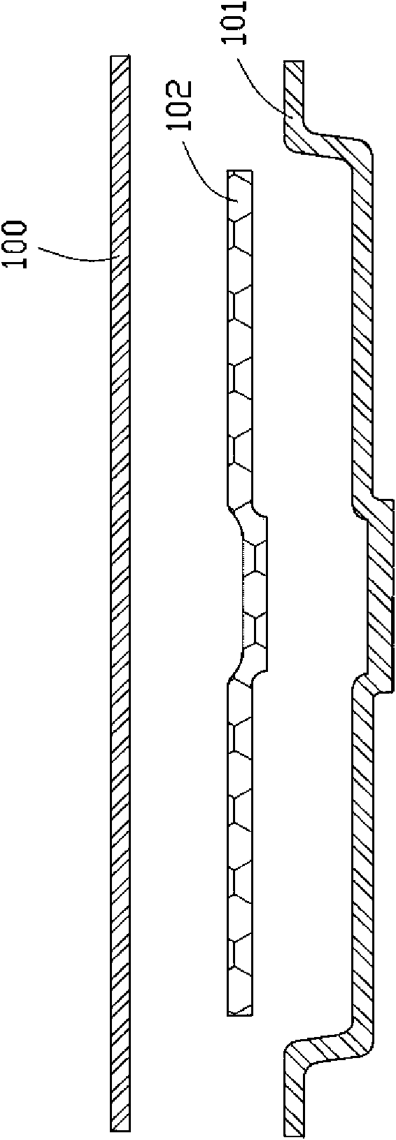
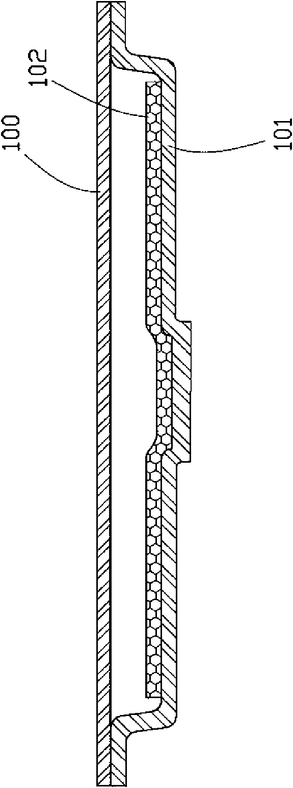
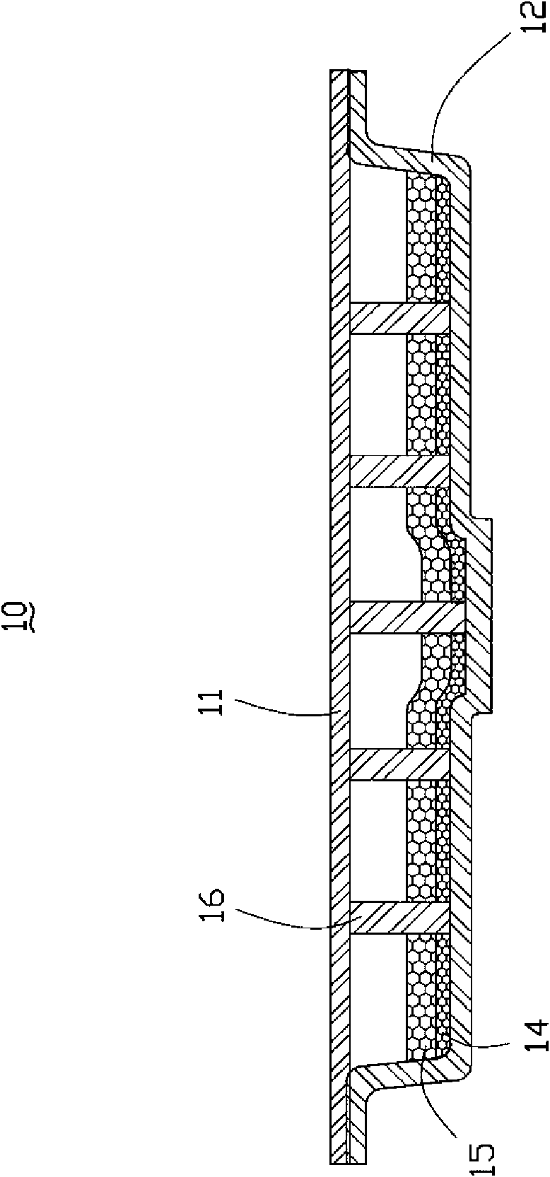
[0022] like image 3 As shown, it is the flat heat pipe 10 of the first embodiment of the present invention, and its specific manufacturing process is as follows: (1) provide a metal upper cover plate 11, a metal lower cover plate 12 matched with the upper cover plate 11, and the Above-mentioned upper cover plate 11 and lower cover plate 12 are all made by stamping, and this lower cover plate 12 is arranged in bowl shape so that its middle part has an accommodating space, and this upper cover plate 11 is flat plate-shaped arrangement; (2) provide several second A metal powder, these metal powders are sintered to form a number of dense solid support columns 16; (3) one end of these support columns 16 is vertically arranged on the upper surface of the lower cover plate 12, and the height of the corresponding support columns 16 is the same as The distances between the corresponding positions of the upper and lower cover plates 11 and 12 are equivalent; (4) provide the second meta...


PUM


Abstract

The invention relates to a method for manufacturing a flat-plate heat tube. The method comprises the following steps: (1) providing an upper cover plate and a lower cover plate; (2) providing a plurality of first metal powders, and after being sintered, the first metal powders form a plurality of supporting columns; (3) arranging one end of each of the supporting columns on the upper surface of the lower cover plate, and correspondingly, the height of each supporting column is equivalent to the distance between the corresponding positions of the upper cover plate and the lower cover plate; (4)providing a plurality of second and third metal powders, filling the bottom of the lower cover plate with the metal powders, arranging the metal powders in the way of surrounding the supporting columns, and sintering the lower cover plate at a high temperature so as to enable the second metal powders to form a first capillary structure attached to the upper surface of the lower cover plate and toenable the third metal powders to form a second capillary structure attached to the upper surface of the first capillary structure; (5) welding the supporting columns and the lower cover plate on thelower surface of the upper cover plate so as to form a rough blank; and(6) processing the rough blank by vacuum-pumping, working fluid injection, degasification, sealing and surface heat treatment, thereby obtaining the final product of the flat-plate heat tube.

Description

technical field [0001] The invention relates to a method for manufacturing a flat heat pipe, in particular to a method for manufacturing a flat heat pipe with a composite capillary structure. Background technique [0002] At present, heat pipes are commonly used in the industry to solve the high-density heat dissipation problem of high-speed computers, such as heat pipes, loop heat pipes, and flat heat pipes (Vapor Chamber) and other products. [0003] The working principle of the flat heat pipe is the same as that of the traditional heat pipe. Because it has a larger heat conduction area than the traditional heat pipe, and meets the high practical value of "light, thin, short, and small", it is widely used in electronic products with large heat dissipation surfaces. superior. [0004] like figure 1 and figure 2 As shown, a general flat heat pipe has an upper cover 100 prepared by a stamping process, a lower cover 101 matched with the upper cover 100 , and a capillary st...

Claims


Application Information

Patent Timeline
Patent Type & Authority Applications(China)
IPC IPC(8): F28D15/02B22F3/10
Inventor 侯春树
Owner FU ZHUN PRECISION IND SHENZHEN
Why Eureka
Try Eureka