
Lens, method for removing lens flare and die for manufacturing lens barrel

A lens and lens barrel technology, applied in optics, optical components, instruments, etc., can solve glare and other problems, achieve the effect of improving brightness quality, increasing transparency, and retaining image details

Inactive Publication Date: 2010-02-03
BYD CO LTD
View PDF0 Cites 13 Cited by
  • Summary
  • Abstract
  • Description
  • Claims
  • Application Information

AI Technical Summary

Problems solved by technology

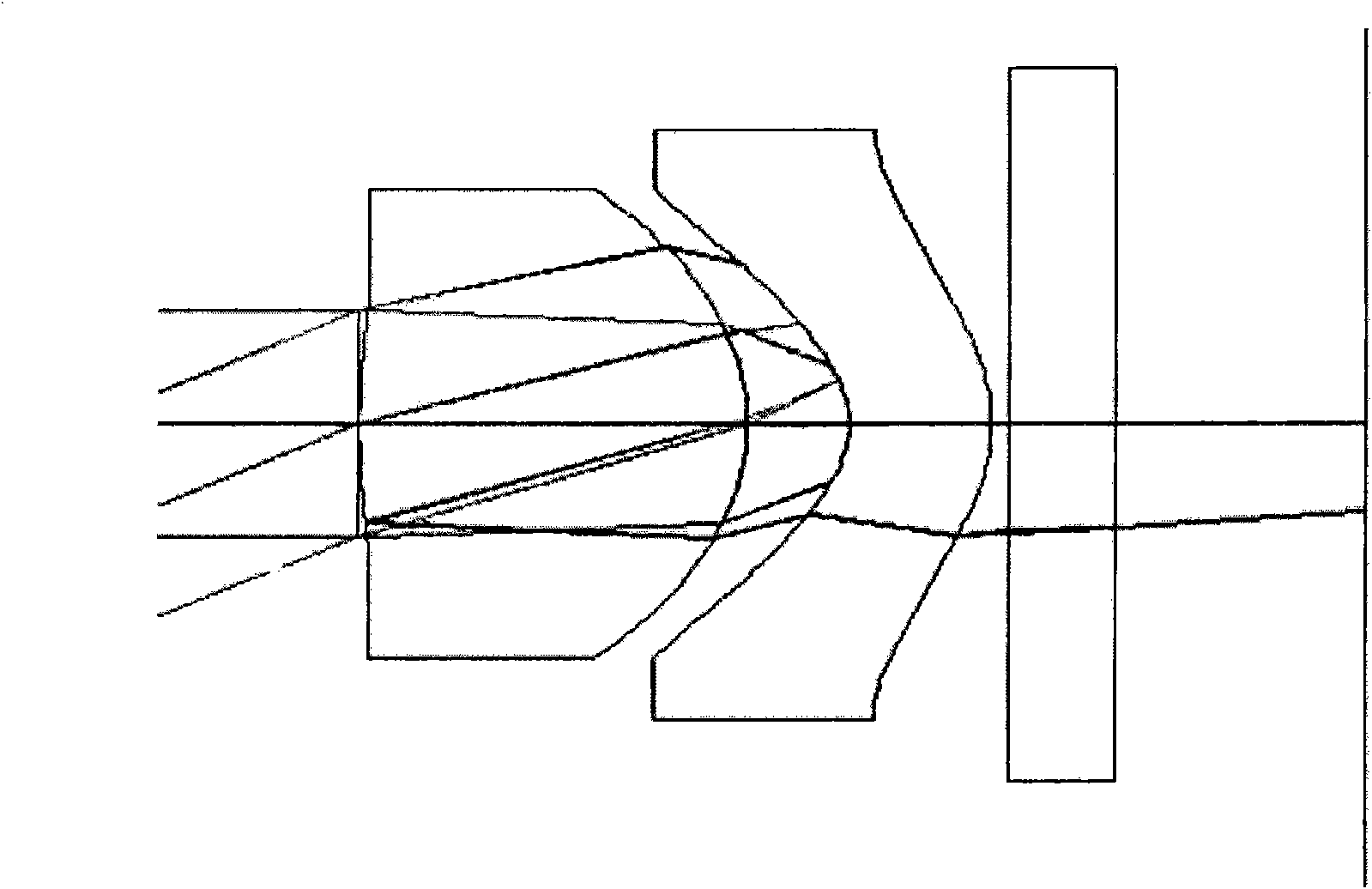
Regardless of the resin lens or the glass lens, due to the limitation of its own physical factors, about 5% of the light will be reflected (such as Figure 7 shown by the dotted line), resulting in the formation of glare

Method used


Image

  • Lens, method for removing lens flare and die for manufacturing lens barrel
  • Lens, method for removing lens flare and die for manufacturing lens barrel
  • Lens, method for removing lens flare and die for manufacturing lens barrel

Examples


Embodiment Construction

[0023] Specific embodiments of the present invention will now be described in detail, examples of which are illustrated in the accompanying drawings, wherein identical or similar reference numerals designate identical or similar elements. The present invention is described below by referring to the accompanying drawings, which are only for explaining the present invention, but not construed as limiting the present invention.

[0024] It should be noted that, in the description of the present invention, the terms "first", "second" and so on are only for the convenience of description of the present invention, and shall not be construed as limiting the present invention.

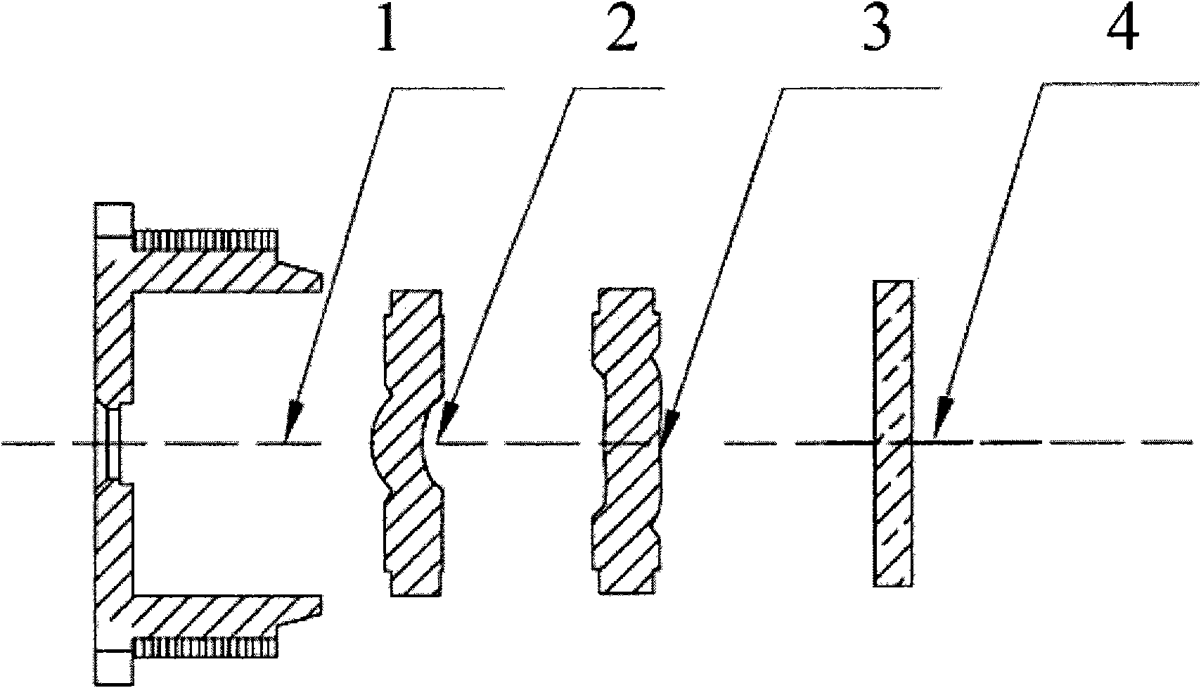
[0025] A lens according to an embodiment of the present invention will be described below with reference to the drawings. figure 1 It is a schematic diagram of assembly of a lens according to an embodiment of the present invention, such as figure 1 As shown, the lens includes a lens barrel 1 , a first lens ...


PUM


Abstract

The invention discloses a lens, a method for removing lens flare and a die for manufacturing a lens barrel. The lens comprises the lens barrel and a first lens sheet, a second lens sheet and an infrared light filter which are arranged in the lens barrel in turn, wherein the surface of at least one of the first lens sheet, the first lens sheet and the infrared light filter is provided with a coating film for reducing ray reflection. The lens, the method for removing the lens flare and the die for manufacturing the lens barrel can increase the permeability of the lens, weaken the ray reflection,and effectively inhibit the production of the flare.

Description

technical field [0001] The invention relates to the technical field of optical imaging, in particular to a lens, a method for removing lens glare and a mold for manufacturing a lens barrel of the lens. Background technique [0002] Optical imaging devices are prone to glare during the imaging process, which affects the brightness and clarity of imaging. There are many reasons for glare. [0003] For a lens under ideal conditions, light can completely pass through the lens to reach the photosensitive medium. However, in actual situations, when the light passes through the front and rear surfaces of the lens, not only refraction but also reflection will occur. Part of the light will be reflected on the surface of the lens, reducing the light reaching the photosensitive medium, resulting in a decrease in image quality and a decrease in the brightness of the image. At the same time, because the lens is assembled from several groups of different lenses, the light will produce g...

Claims


Application Information

Patent Timeline
IPC IPC(8): G02B7/02G02B1/11G02B1/10
Inventor 黄阳吉雷延录
Owner BYD CO LTD
Learn More