
Device for automatic material stripping and automatic Bin splitting for serial flaky LEDs

An automatic, flaky technology, applied in the direction of electrical components, circuits, semiconductor devices, etc., can solve problems such as error-prone, low efficiency, poor equipment compatibility, etc., and achieve the effect of reducing process requirements, improving efficiency, and strong versatility

Inactive Publication Date: 2010-02-03
HANGZHOU ZHONGWEI PHOTOELECTRICITY
View PDF0 Cites 4 Cited by
  • Summary
  • Abstract
  • Description
  • Claims
  • Application Information

AI Technical Summary

Problems solved by technology

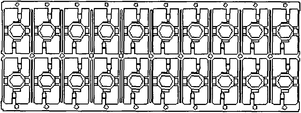
[0003] With the sharp increase in market demand for LEDs, the output of various manufacturers is also increasing steadily. However, at present, the classification and loading of strip-shaped LEDs is basically done by stripping the stripping mechanism or manually after packaging. Bulk materials are tested by manual equipment and manually classified according to the test results. The operation is very inconvenient, error-prone, and the efficiency is very low. The average efficiency is 1K / h, which cannot meet the current market demand for LED rapid growth; at present, there is another The solution is to peel off the stripped strip LEDs after packaging, then manually fill the single bulk material into a special material tube, and then put the material tube on the automatic spectroscopic sorting equipment for spectroscopic separation. The disadvantage of this solution is that there are many processes and equipment, and at the same time, the automatic spectroscopic sorting equipment is expensive, and a fully automatic spectroscopic sorting LED packaging quality and consistency requirements are very high, therefore, there are also disadvantages of low efficiency, poor equipment compatibility, and high equipment configuration costs

Method used


Image

  • Device for automatic material stripping and automatic Bin splitting for serial flaky LEDs
  • Device for automatic material stripping and automatic Bin splitting for serial flaky LEDs
  • Device for automatic material stripping and automatic Bin splitting for serial flaky LEDs

Examples


Embodiment 1

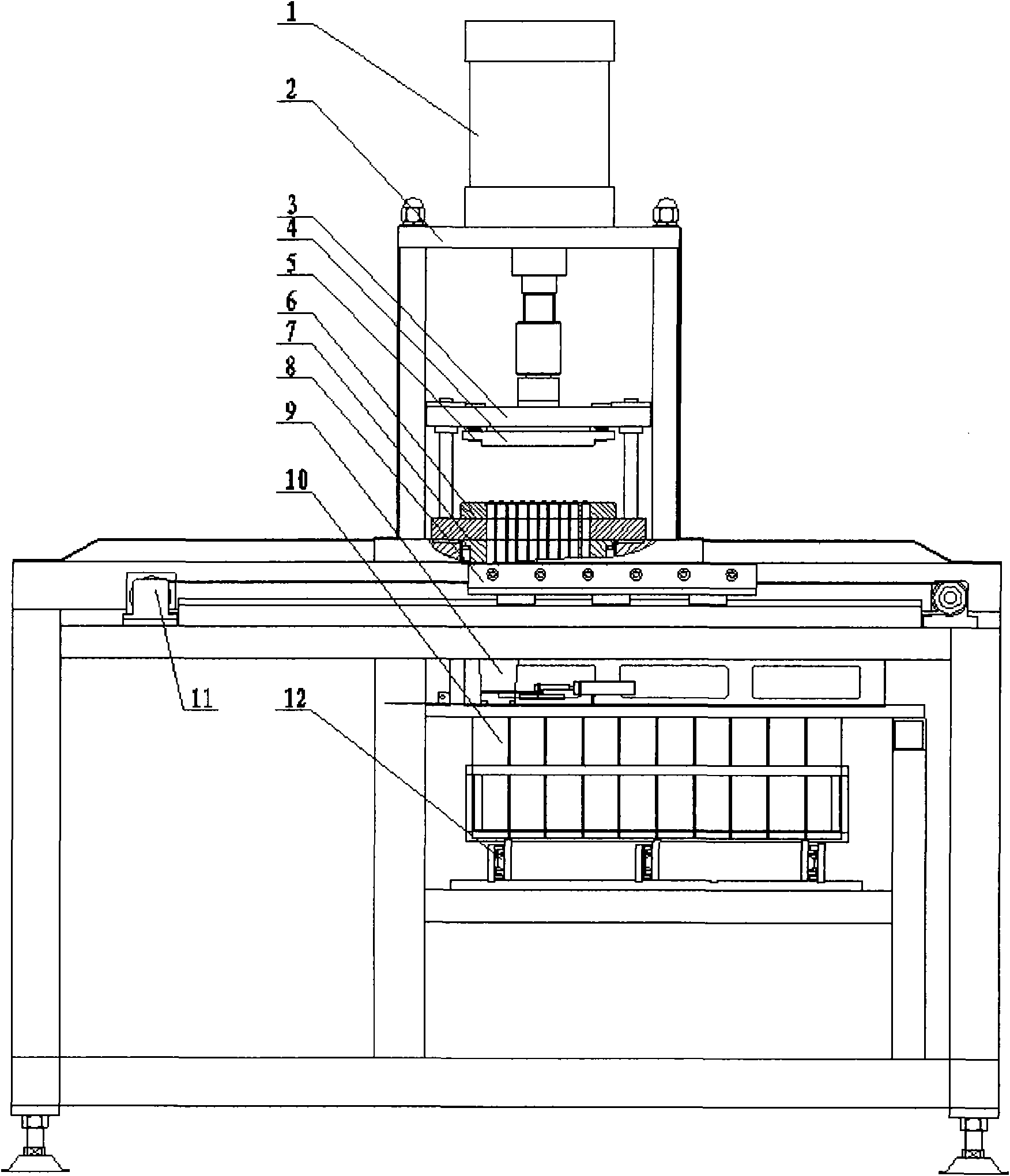
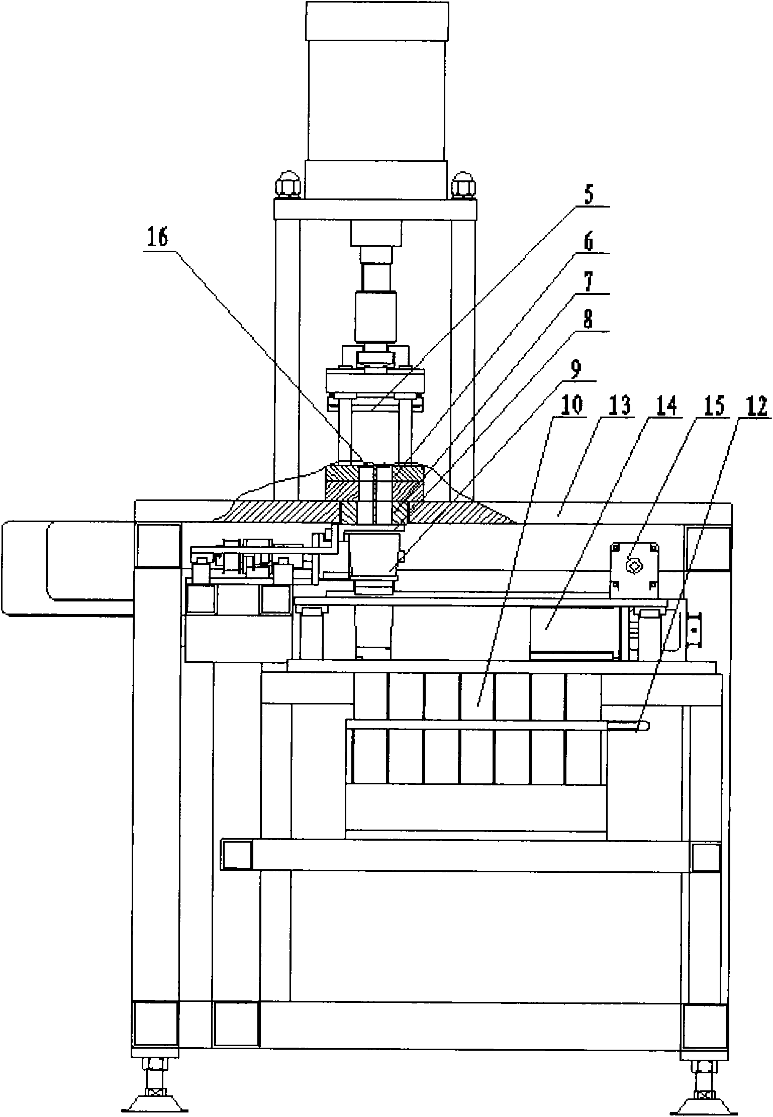
[0021] Such as figure 1 , figure 2 As shown in the structure, the row-by-row chip LED automatic stripping and binning equipment is composed of four major parts: automatic stripping mechanism, sequential discharging escapement mechanism, X / Y automatic material shifting mechanism, and sorting and collecting mechanism; pressure cylinder 1 is installed On the pressure cylinder bracket 2, the piston rod of the pressure cylinder 1 is connected with the four guide post mold base 3 through threads, the punch 4 and the blank holder 5 are located on the upper template of the mold base 3, and the die 6 is positioned on the lower side of the mold base 3 On the template, the transitional separation mold 7 is fastened to the bottom of the die 6, and the corresponding positions of the die 6, the lower formwork, and the transitional separation mold 7 are all opened with small square holes, the number of rows of small square holes and the number of holes in each row The number is determined ...


PUM


Abstract

The invention discloses a device for automatic material stripping for LEDs, in particular to a device for automatic material stripping and automatic Bin splitting for serial flaky LEDs. The device ofthe invention is characterized by comprising an automatic material stripping mechanism, a sequential material discharging escapement mechanism, an X / Y automatic material transferring mechanism, a swinging material receiving box, a classified material collecting box, a classified material collecting mechanism and a detecting system, wherein the automatic material stripping mechanism is positioned on a worktable plate of a stand, and the serial flaky LEDs comprise a plurality of LEDs which are positioned on a mold of the automatic material stripping device. The invention has the advantages of greatly improving the compatibility and the universality of the device and reducing the technological requirements for the products of manufacturers, and meanwhile, the device has small impact and shockand can be operated and maintained conveniently, thereby greatly reducing the assembly cost of the devices of the manufacturers. The device of the invention can be widely used for the manufacturers producing or using LEDs.

Description

technical field [0001] The invention relates to a device integrating material stripping and binning, in particular to a device for automatically stripping and binning LEDs in rows. technical background [0002] As a power type semiconductor device, LED is also a very effective new light source. Its optical structure concentrates the emitted light almost without loss, and emits it through a narrow structure. Its color is currently red. , green, blue and white light. The advantages of LED are high brightness, low working voltage, low power consumption, miniaturization, easy matching with integrated circuits, simple driving, long life, impact resistance, and stable performance. As a new green light source for energy saving and environmental protection, it has been widely used in the background Screens, landscape lights, street lights, interior decoration and other occasions, it is believed that with the development of technology and the demand for energy conservation and envir...

Claims


Application Information

Patent Timeline
Patent Type & Authority Applications(China)
IPC IPC(8): H01L33/00
Inventor 张九六
Owner HANGZHOU ZHONGWEI PHOTOELECTRICITY
Learn More