
Microchannel cooling device of kilowatt level optical fiber laser

A fiber laser and cooling device technology, applied in the field of cooling devices, can solve problems such as fiber side burnout, fiber laser not working normally, output wavelength change, etc., and achieve the effects of prolonging service life, obvious cooling effect, and uniform heat dissipation

Inactive Publication Date: 2010-02-03
WUHAN INSTITUTE OF TECHNOLOGY
View PDF0 Cites 10 Cited by
  • Summary
  • Abstract
  • Description
  • Claims
  • Application Information

AI Technical Summary

Problems solved by technology

However, as the output power continues to increase, especially when the laser output reaches the kW level, the thermal diffusion of the matrix material will cause stress and changes in the refractive index. Due to heat deposition, the temperature in the doped fiber core will increase and the quantum efficiency will decrease. , the output wavelength changes, and even lead to matrix melting, fiber end face damage, burning of the fiber side incision, and fiber side burning, so that the fiber laser cannot work normally

Method used


Image

  • Microchannel cooling device of kilowatt level optical fiber laser
  • Microchannel cooling device of kilowatt level optical fiber laser
  • Microchannel cooling device of kilowatt level optical fiber laser

Examples


Embodiment Construction

[0014] The present invention will be further described below in conjunction with the embodiments and accompanying drawings, but the protection scope of the present invention should not be limited thereby.

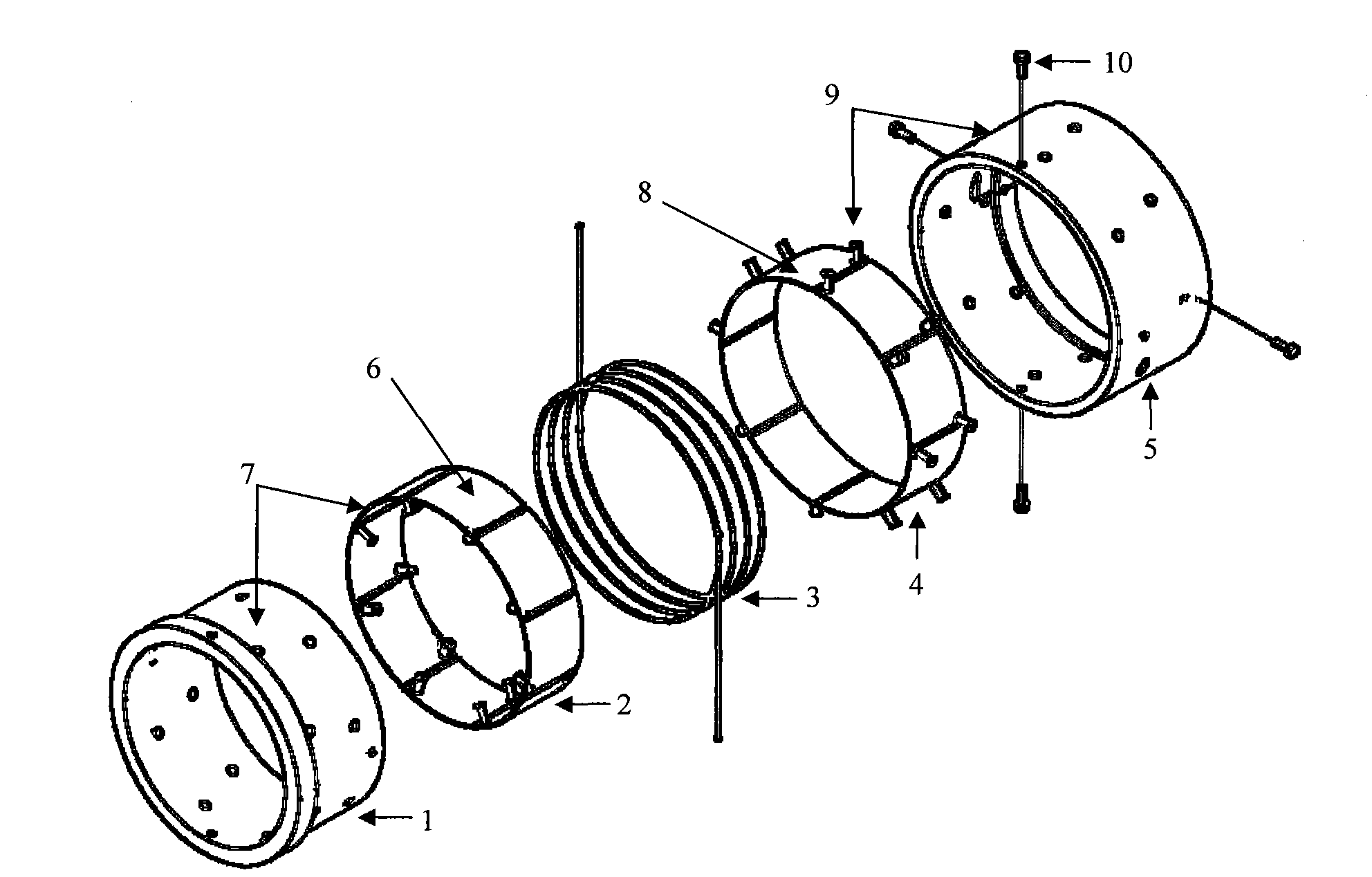
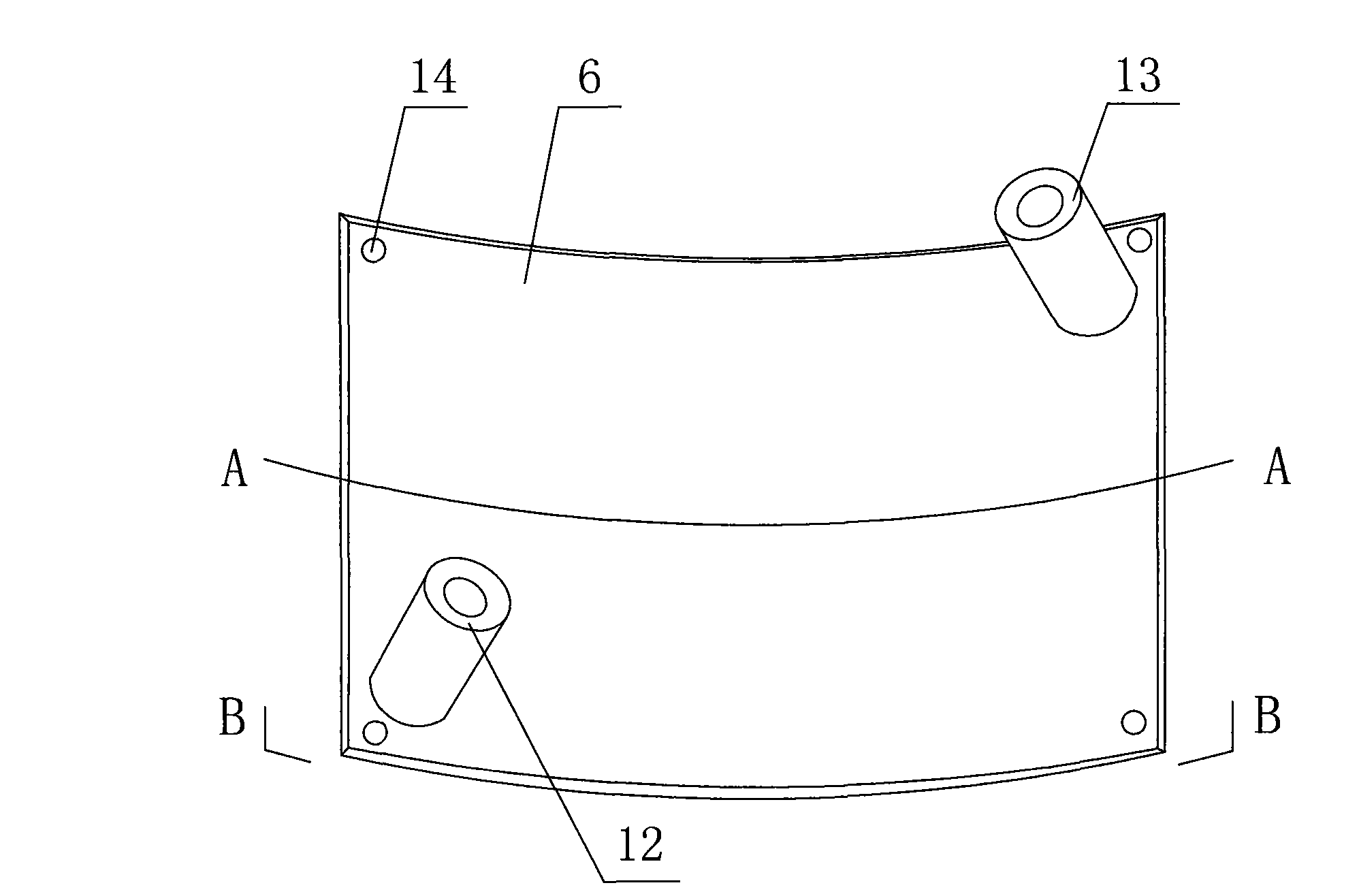
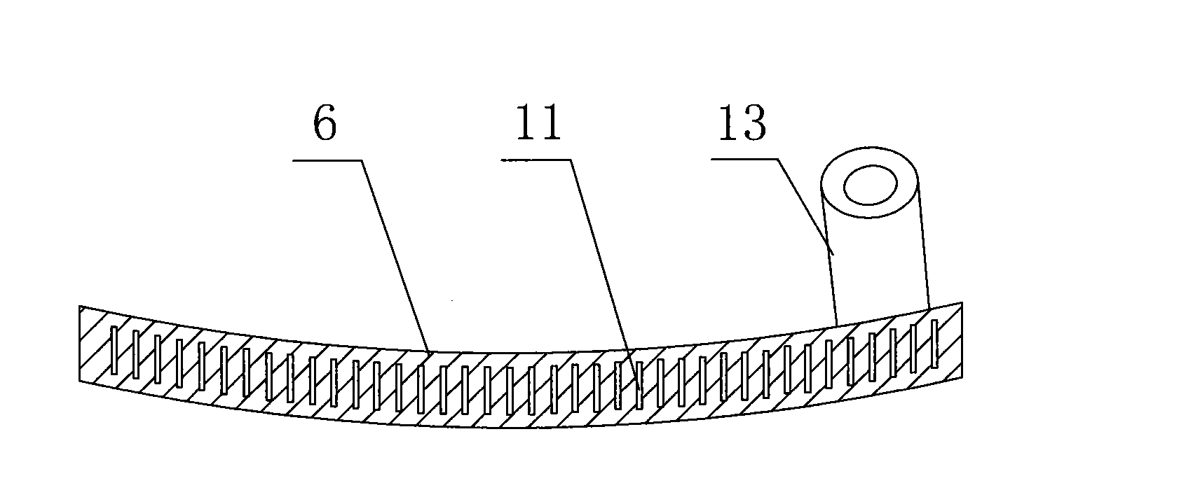
[0015] Such as figure 1 , figure 2 , image 3 , Figure 4 As shown, the kilowatt-class fiber laser microchannel cooling device includes an inner cooler 7 and an outer cooler 9, and the outer cooler 9 is set on the inner cooler 7; when in use, the fiber laser 3 (kilowatt-class fiber laser) is located inside between the cooler 7 and the outer cooler 9, and the fiber laser 3 is wound on the inner cooler 7 and is in contact with the outer cooler 9; the input end of the fiber laser 3 passes through the optical fiber input hole on the outer cooler 9 and is located outside Outside the cooler 9, the output end of the fiber laser 3 passes through the optical fiber output hole on the outer cooler 9 and is positioned outside the outer cooler 9; the outer cooler 9 and the inner coo...


PUM


Abstract

The invention relates to a device used for cooling of a kilowatt level optical fiber laser. A microchannel cooling device of the kilowatt level optical fiber laser is characterized by comprising an inner refrigerator and an outer refrigerator, wherein the outer refrigerator is sheathed on the inner refrigerator; when in use, the optical fiber laser is positioned between the inner refrigerator andthe outer refrigerator, and the optical fiber laser is wound on the inner refrigerator and is contacted with the outer refrigerator; the outer refrigerator and the inner refrigerator are connected byscrews; and the inner refrigerator and the outer refrigerator are made of metal. The device is characterized by even heat dissipation, obvious refrigerating effect and strong practicability and the like.

Description

technical field [0001] The invention relates to a cooling device for a kilowatt-class fiber laser. Background technique [0002] Since E. Snitzer and others proposed the concept of double-clad fiber in 1988, fiber lasers based on this cladding pumping technology have achieved rapid development. In 2007, the single-fiber output power has reached 3kW, and the multi-fiber coupling technology has been used to complete tens of thousands of watts of fiber lasers in the laboratory. [0003] Compared with traditional solid-state lasers, high-power double-clad fiber lasers have a large surface area to volume ratio, and can effectively dissipate the heat deposited by pumping light when working at low power. However, as the output power continues to increase, especially when the laser output reaches the kW level, the thermal diffusion of the matrix material will cause stress and changes in the refractive index. Due to heat deposition, the temperature in the doped fiber core will incre...

Claims


Application Information

Patent Timeline
IPC IPC(8): H01S3/042H01S3/067
Inventor 刘国华
Owner WUHAN INSTITUTE OF TECHNOLOGY
Learn More