Nano water ion generating device

An ion generating device and nano-water technology, which is applied to machines that use electric/magnetic effects, machine operation methods, electrical components, etc., can solve the problem of inability to manufacture nano-water ions stably for a long time, inability to exert water absorption/retaining effects, Increase the difficulty of assembly or processing to achieve the effect of improving refrigeration efficiency and cold transfer efficiency, ensuring long-term safe operation, and increasing service life

Active Publication Date: 2019-07-05
HANGZHOU DAZHAN ELECTROMECHANICAL TECH CO LTD
View PDF4 Cites 11 Cited by
  • Summary
  • Abstract
  • Description
  • Claims
  • Application Information

AI Technical Summary

Problems solved by technology

[0003] (1) Unstable condensed water: Comparative documents 1-3 all use the method of condensing water at the tip of the discharge electrode to produce nano-water ions. Due to the existence of the heat transfer temperature gradient, in order to condense water from the air throughout the year, The tip of the discharge electrode needs to maintain an extremely low temperature, resulting in a large waste of power consumption. In summer, when the temperature is high and the air humidity is high, the discharge electrode often condenses excessively, and a special water absorption or water retaining mechanism needs to be installed, which not only increases It is difficult to assemble or process, and the water-absorbing and water-retaining mechanism on the outer cover or the water-absorbing structure formed by the hollow inside the discharge electrode often fails and cannot play the role of water absorption / water-retaining. In winter, when the temperature is low and the air humidity is low, the discharge electrode often frosts Or freeze, resulting in the inability to generate nano water ions
[0004] (2) The discharge electrode is easy to corrode: compared with documents 1-3, the discharge electrode is a metal needle, which is not only used to condense water, but also used for discharge. With the increase of use time, the discharge tip of the discharge electrode is easy to wear and rough surface, resulting in unstable tip discharge and unable to produce nano water ions stably for a long time
[0005] (3) The high-voltage electric field is unstable: compared with documents 1-3, due to the lack of necessary high-voltage constant voltage / positioning mechanism, when a high voltage is applied between the discharge electrode and the high-voltage electrode, high-voltage voltage drift or discharge current shock is likely to occur. The semiconductor grains that are directly connected to the discharge electrodes are broken down, which poses a safety hazard

Method used


Image

  • Nano water ion generating device
  • Nano water ion generating device
  • Nano water ion generating device

Examples


Embodiment 1

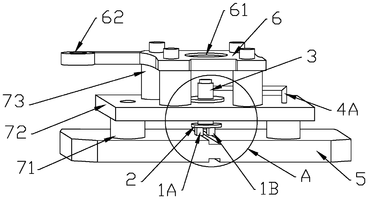
[0036] refer to figure 1 , 2 , the present embodiment provides a nanometer water ion generating device, including a pair of semiconductor grains composed of a P-type semiconductor 1A and an N-type semiconductor 1B, one end of the semiconductor grain pair is a cooling end, and the other end is a heat dissipation end ; Also includes a condensation pan 2, a discharge electrode 3 and a constant voltage electrode; the condensation pan 2 is electrically connected to the cooling end of the semiconductor crystal grain pair; the discharge electrode 3 is arranged above the condensation pan 2 One end of the discharge electrode 3 is a water-absorbing end, and the water-absorbing end is close to the condensation plate 2, and the other end of the discharge electrode 3 is a discharge end; the constant voltage electrode is arranged on the side of the discharge electrode 3 .

[0037]Specifically, during the working process, the temperature at the condensation pan 2 is slightly lower than the...

Embodiment 2

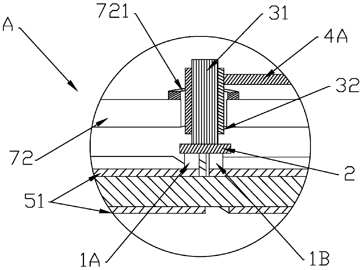
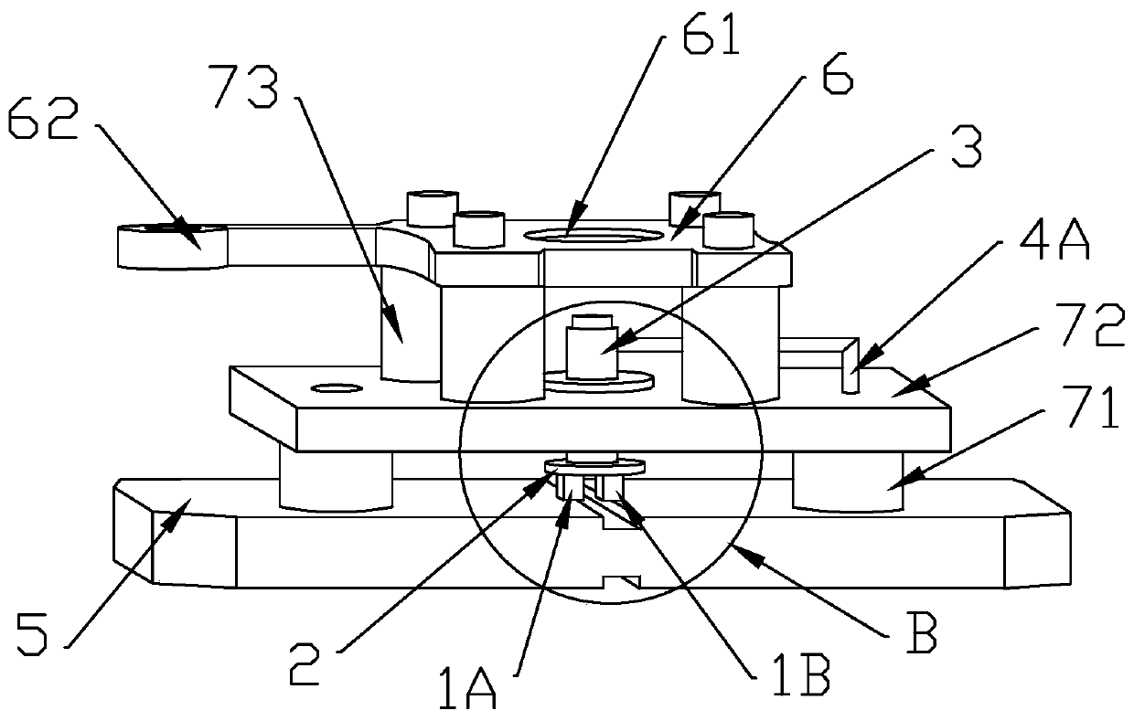
[0063] refer to image 3 , 4 , on the basis of the first embodiment, this embodiment also includes a positioning pin 21, and the positioning pin 21 is arranged on the condensation pan 2.

[0064] Specifically, the positioning pin 21 can be integrally formed with the condensation pan 2 or welded and fixed to the center of the condensation pan 2 to support and position the discharge electrode 3, and the positioning pin 21 with a lower temperature can also be Liquid droplets are directly condensed on the conductor wires / bundles 31 inside the discharge electrode 3 to increase the amount of condensed water.

Embodiment 3

[0066] refer to Figure 5 , 6 , on the basis of Embodiment 1, the constant voltage electrode 4B used in this embodiment is a conductor perpendicular to the discharge electrode 3, and the constant voltage electrode 4B points to one end of the discharge electrode 3 and the The conductor cladding layer 51 on the side close to the pair of semiconductor crystal grains is electrically connected, and the other end of the constant voltage electrode 4B is electrically connected to the regulated power supply.

[0067] Specifically, the side of the constant voltage electrode 4B pointing to the discharge electrode 3 is fixed on the support table 72 by screws, and is electrically connected to the conductor coating 51 on the side close to the pair of semiconductor crystal grains.


PUM


Abstract

The invention relates to a nano water ion generating device, which comprises a semiconductor crystal grain pair consisting of a P-type semiconductor and an N-type semiconductor. One end of the semiconductor crystal grain pair is a refrigerating end, and the other end of the semiconductor crystal grain pair is a radiating end. The nano water ion generating device also comprises a water condensationdisc, a discharge electrode and a constant voltage electrode; the water condensation disc is electrically connected with the refrigerating end of the semiconductor crystal grain pair; one end of thedischarge electrode is a water absorption end, the water absorption end is close to the water condensation disc, and the other end of the discharge electrode is a discharge end; and the constant voltage electrode is arranged on the side part of the discharge electrode. The nano water ion generating device can be applied to the fields of air purification, sterilization, cosmetology and hairdressing, moisture preservation, fresh keeping and the like.

Description

technical field [0001] The invention relates to a nanometer water ion generating device, which belongs to the fields of air purification, sterilization, hairdressing, moisturizing and fresh keeping. Background technique [0002] Nano-water ions have a small particle size of 5-60nm, a long life span of up to 10 meters, a high water content of 1000 times that of negative ions, weak acidity, affinity for hair and skin, efficient cleaning, decomposition of formaldehyde VOCs, deodorization, and PM2 smog removal .5. With many advantages such as sterilization and disinfection, hairdressing, moisturizing and fresh-keeping, it has gradually become a research hotspot in the fields of air purification, formaldehyde and odor removal, sterilization and disinfection, moisturizing and fresh-keeping, beauty and hairdressing, and personal care. Existing nano-water ion generators, such as reference document 1 application number 2016020403170.9 provides a nano-water ion air purification device...

Claims


Application Information

Patent Timeline
Patent Type & Authority Applications(China)
IPC IPC(8): H01T23/00F25B21/02
CPCF25B21/02H01T23/00
Inventor 唐峰代星杰姜峰
Owner HANGZHOU DAZHAN ELECTROMECHANICAL TECH CO LTD
Why Eureka
Try Eureka