
Heat-ray sensor

A technology of infrared detectors and detection components, applied in instruments, using electric radiation detectors for photometry, alarms, etc., can solve the problems of difficult to maintain the alarm area, difficult to distinguish human insects, etc., to prevent the generation of wrong information Effect

Active Publication Date: 2010-02-03
ATSUMI ELECTRIC CO LTD
View PDF0 Cites 8 Cited by
  • Summary
  • Abstract
  • Description
  • Claims
  • Application Information

AI Technical Summary

Problems solved by technology

[0004] However, prior art passive infrared detectors are effective in preventing false information from being generated at locations where a person who is the subject of detection walks (typically at a location about 2m-30m away from the passive infrared detector)
Therefore, it is difficult to maintain a sufficient warning zone and is thus ineffective in preventing the generation of false information related to small animals moving close to the passive infrared detector
Although a passive infrared detector utilizing multiple optical elements with wide spacing between them has been proposed, it is difficult to maintain a sufficient distance for small animals because the purpose of providing wide spacing is different from preventing the generation of false information. Distinguishing between human body (human) and insects or birds flying near the detector or crawling onto the surface of the detector

Method used


Image

  • Heat-ray sensor
  • Heat-ray sensor
  • Heat-ray sensor

Examples


Embodiment Construction

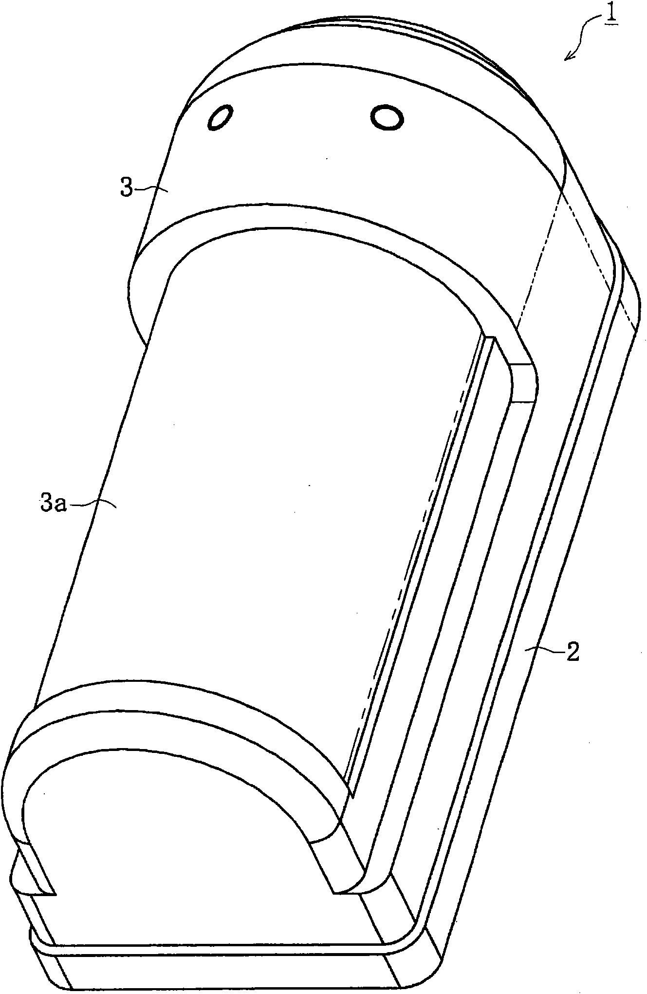
[0047] Such as Figure 1-3 As shown, a passive infrared detector 1 generally includes a rectangular base 2 having a longer vertical side in front view and a cover 3 detachably mounted on the front side of the base 2 and adapted to Installed on a mounting surface such as a wall, the cover 3 has a window capable of transmitting far-infrared radiation and an optical unit 4 inside the cover 3 .

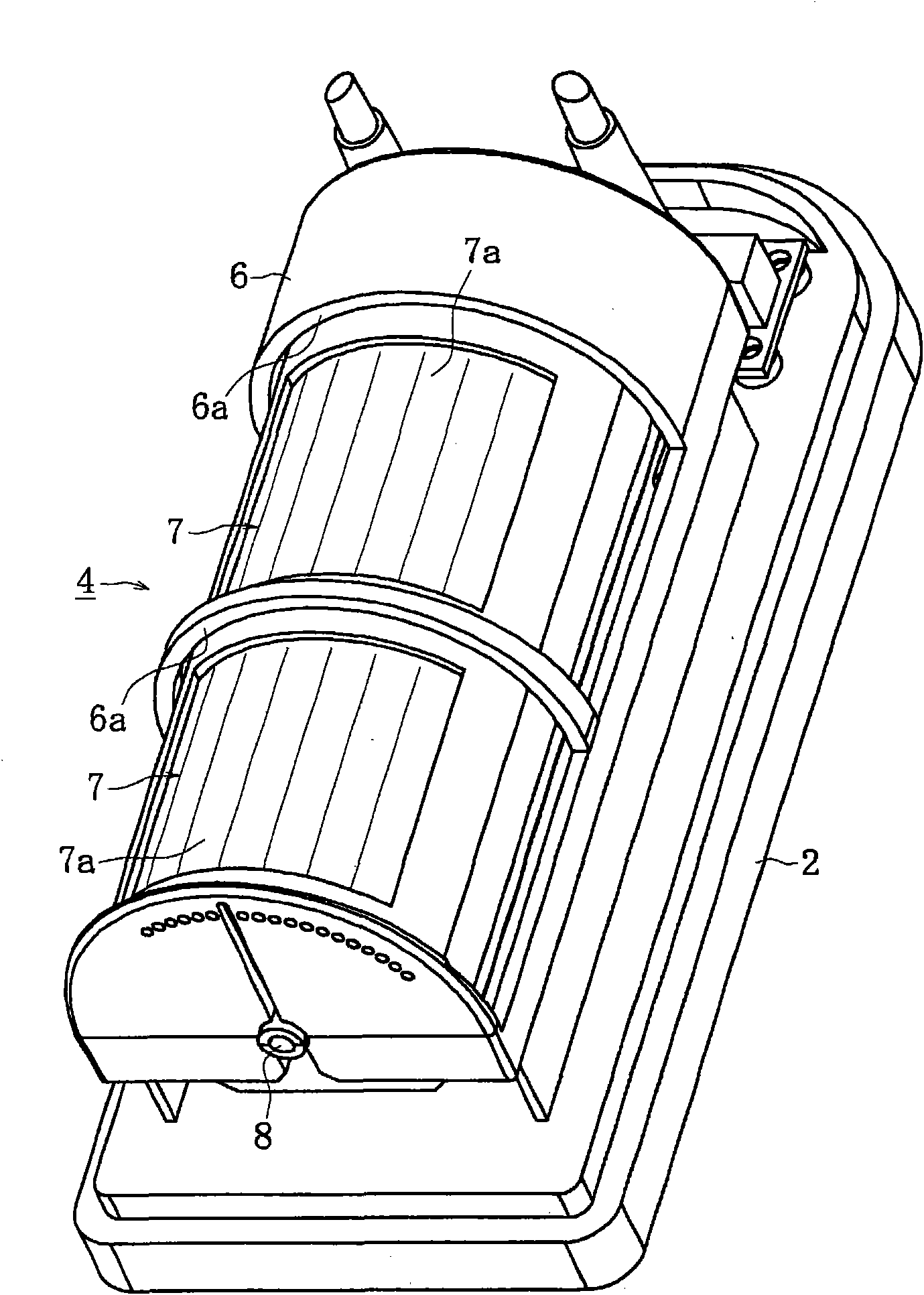
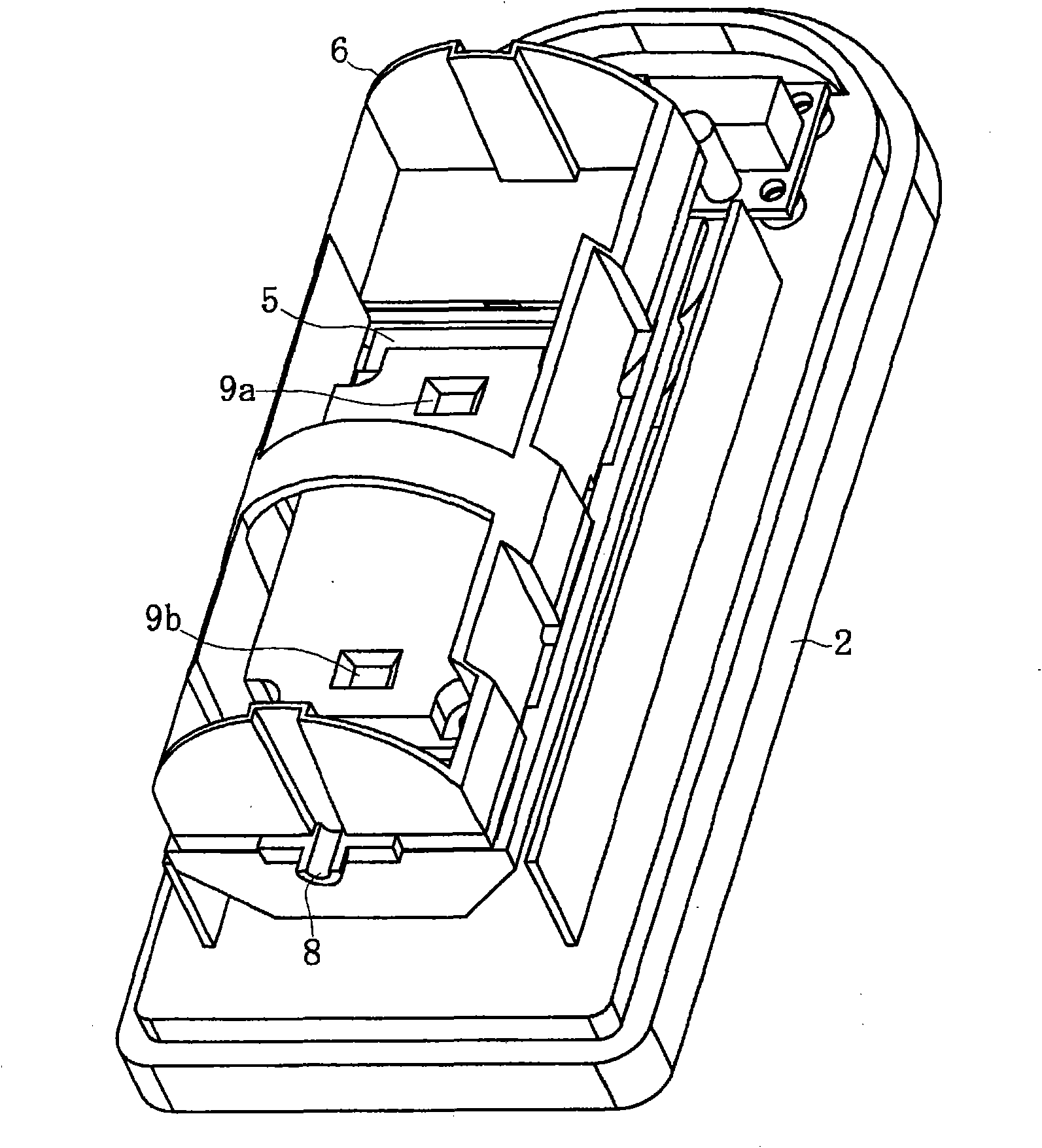
[0048] Such as figure 2 As shown, the optical unit 4 has a housing 6 having a pair of openings 6a located at vertically spaced positions, in which the pair of openings 6a comprising a plurality of lenses 7a (or a pair of mirror assemblies comprising a plurality of mirrors) are disposed. A pair of vertically spaced apart lens assemblies 7, and a PCB (printed circuit board) 5 ( image 3 ). The interval between the vertically arranged lens assemblies 7 is set such that it is small for the size of the human body M (intruder) and large for the size of the small animal T. FIG. The lens ass...


PUM


Abstract

An object of the present invention is to provide a passive infrared detector which can surely discriminate an intruder and a small animal passing proximately to the detector without detracting the performance for detecting the intruder within the guard coverage area (alert object area). According to the present invention, there is provided a passive infrared detector for detecting a moving objectsuch as intruder comprising an optical unit having a PCB (print circuit board) disposed in front of a base and mounted thereon a plurality of lenses vertically arranged at predetermined spaces and detecting elements arranged at positions corresponding to the lenses, and a control means for processing signals detected by the detecting elements characterized in that the spaces between the pluralityof lenses are set so that they are small for a size of a human body and large for a size of a small animal, and that the control means are adapted to judge whether the moving object is an intruder ora small animal by discriminating the simultaneity of signals detected by the detecting elements or by summing the detected signals.

Description

technical field [0001] The present invention relates to a passive infrared detector for detecting an intruder as a moving object by detecting thermal changes of far-infrared radiation from a human body by using a pyroelectric element. Background technique [0002] Typically, a passive infrared detector includes a housing or container formed from a plurality of mirrors and an optical unit mounted on the tip of a pair of side walls extending from the end of the housing and including a PCB (Printed Circuit Board) of pyroelectric element, this passive infrared detector is suitable for detecting intruders (i.e. human body) within the guard coverage area (alarm object area) by detecting thermal changes of far-infrared radiation using the pyroelectric element . [0003] In this passive infrared detector, there is provided a method of forming a single system in one optical unit by using a plurality of elements arranged with a plurality of pyroelectric elements, or by utilizing a pa...

Claims


Application Information

Patent Timeline
Patent Type & Authority Applications(China)
IPC IPC(8): G01J1/42G01J1/02G01V8/12G08B13/191G01V8/10H03K17/945
CPCH03K2217/94116H03K17/941G01J5/0893G01J5/0025G01J5/025G01J5/08G01J5/0022G01J5/0846G01J5/026G01J5/089G01J5/0806H03K2217/94112G08B13/191H03K2217/94106G01J5/02G01J5/07
Inventor 泽谷一幸
Owner ATSUMI ELECTRIC CO LTD
Learn More