Detection of visible light communication sources over a high dynamic range

a visible light communication and high dynamic range technology, applied in the field of visible light communication, can solve the problems of difficult environment for detecting dim signals or signals, application of light-based communication, blooming artifacts, etc., and achieve the effect of high dynamic range (hdr) image, optimal exposure duration and higher frame ra

Active Publication Date: 2019-01-29
FORD GLOBAL TECH LLC
View PDF13 Cites 21 Cited by
  • Summary
  • Abstract
  • Description
  • Claims
  • Application Information

AI Technical Summary

Benefits of technology

[0009]In order to reliably distinguish one or more VLC sources among a collection of objects over a wide range of intensities within the same visual scene, the present invention first obtains a high dynamic range (HDR) image. In a preferred embodiment, the HDR image may be based on a series of image frames captured at varying exposure durations which are fused into a single composited dynamic range image. A sequence of one or more HDR images and / or the captured image frames are searched for evidence of LiFi light sources based on their having a temporal variation (image to image capture) and / or a spatial variation (e.g., due to the artifacts of a CMOS camera rolling shutter). In addition to detecting the locations of VLC sources (i.e., their subwindow “footprint” in the image frame), the HDR image is also used to determine an optimal exposure duration for each respective VLC source. For example, an average or median value (e.g., brightness) of the pixels within the subwindow (i.e., bounding box) containing an individual source (e.g., an LED array) is used to calculate a respective optimal exposure. Alternatively, the optimal exposure can be identified as the minimal exposure time that provides a sufficiently robust differentiation between the ON and OFF states. The optimal exposures preferably are implemented as an exposure time duration, but could also involve adjustment of a camera sensitivity (i.e., ISO setting) or a camera aperture. Using the respective optimized exposures, the identified VLC sources are each viewed separately in their individual field of view (FOV) subwindows. By separately capturing series of images from the subwindows only, a higher frame rate is achieved since only a fraction of the camera's full set of pixels are read out. The use of a higher image capture rate and an optimal exposure time provides the ability to maximize data transfer rates. Subwindowing avoids disadvantages of using a global exposure time which may prevent data transmission from low intensity LED sources altogether or may lower the data transmission rates obtained with higher brightness LED sources.

Problems solved by technology

The outdoor environments for automotive applications of light-based communication pose several significant challenges.
A primary challenge is detecting and reading data transmission from relatively dim LiFi sources in that also include bright ambient light sources such as the sun.
Another challenge is there may be multiple LiFi devices transmitting simultaneously with varying light intensity.
This results in a difficult environment for detecting dim signals or signals where the ON / OFF states are hard to distinguish.
Alternatively, the exposure settings of the camera may result in blooming artifacts when imaging the LiFi transmitter during night time operations.
Photodiodes would offer a large dynamic range in the analog-to-digital response, but they would not be able to distinguish data transmission from LED's of similar intensity since photodiodes do not detect the location of a light source, just the intensity.
Moreover, a photodiode lacks the ability of a camera to localize a LiFi transmitter.
While a camera sensor such as a CMOS-based device would allow discernment between two LED signals of similar intensity, it typically does not have sufficient dynamic range to operate in challenging day time environments with a great amount of ambient light.
Additionally, there are other challenges relating to the varying intensity LiFi signals in an automotive environment interfering with one another and making it difficult to increase data transfer rates.

Method used


Image

  • Detection of visible light communication sources over a high dynamic range
  • Detection of visible light communication sources over a high dynamic range
  • Detection of visible light communication sources over a high dynamic range

Examples


Embodiment Construction

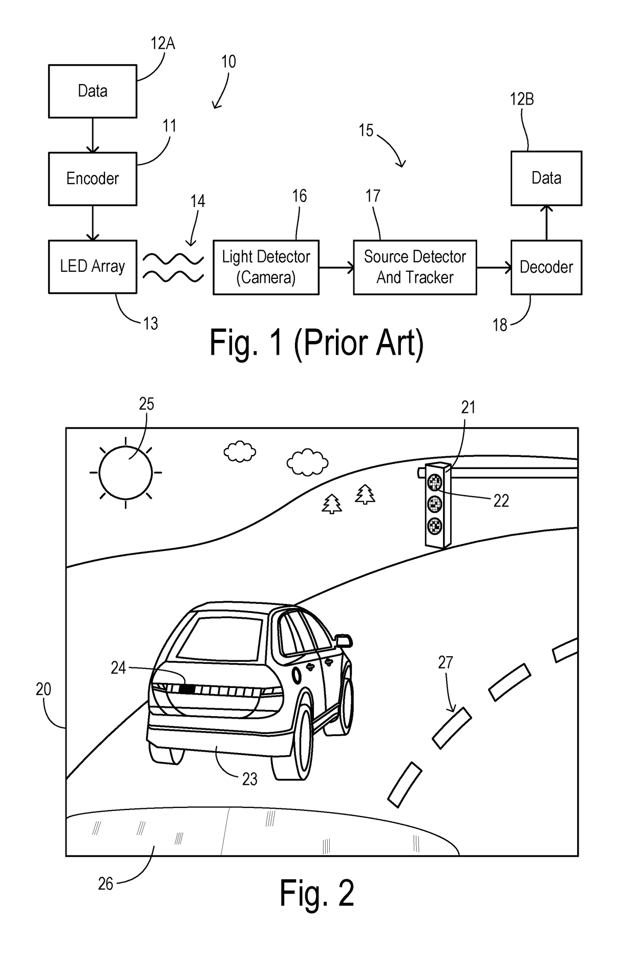
[0023]FIG. 1 shows a conventional visible light communication system having a VLC transmitter 10 and a VLC receiver 15. Transmitter 10 includes an encoder 11 which receives data 12A to be transmitted, and which drives an LED array 13 to emit a flashing VLC light signal according to the encoded data and a chosen communication protocol. LED array 13 may be part of a dual purpose light source which adds the VLC function to a traffic light, vehicle running light, a LCD / OLED display of a mobile device (e.g. a cell phone), fixed display or signage, or other types of artificial lighting applications. Visible light 14 projected from LED array 13 flashes at a high rate which is undiscernible to the human eye but which carries data to a light detector 16 (e.g., a camera) in receiver 15. A source detector and tracker 17 receives a succession of image frames from camera 16, and uses known techniques for identifying any transmitting VLC sources and extracting the flashing signals inherent in the...


PUM


Abstract

A visible light communication (VLC) receiver captures frames of a scene with a camera to detect flashing light signals from a VLC transmitter such as an array of LEDs. The method assembles an enhanced dynamic range image sequence from the frames. At least one VLC source is detected in the enhanced sequence, wherein the source occupies a respective subwindow within the scene. An imaging exposure such as the exposure time used for capturing images at the subwindow is optimized according to a brightness of the respective VLC source. Then a plurality of subwindow images are captured using the optimized exposure. VLC data visible in the subwindow images is then decoded.

Description

CROSS REFERENCE TO RELATED APPLICATIONS[0001]Not Applicable.STATEMENT REGARDING FEDERALLY SPONSORED RESEARCH[0002]Not Applicable.BACKGROUND OF THE INVENTION[0003]The present invention relates in general to visible light communication (VLC) sending digital data, and, more specifically, to detection and isolation of multiple VLC sources in video camera images and optimizing signal-to-noise performance and data transmission speed by capturing subwindowed images for each VLC source.[0004]Visible light based communication (VLC), also referred to as LiFi, is a wireless data communication technology being actively researched for automotive applications and for consumer electronics applications. Data transmission involves modulating (i.e., flashing) a light source such as a light emitting diode (LED) to encode data, and receiving the modulated light at a light sensor such as a photodiode or a camera to decode the data.[0005]A vehicle having a VLC receiver might receive VLC signals from a fi...

Claims


Application Information

Patent Timeline
Patent Type & Authority Patents(United States)
IPC IPC(8): H04B10/116H04N5/359H04B10/67H04N5/353H04N5/3745H04N5/235
CPCH04B10/116H04B10/671H04N5/3597H04N5/3532H04N5/2353H04N5/3745H04N23/743H04N23/73H04N23/741H04N25/77H04N25/531H04N25/626
Inventor HERMAN, DAVID M.INSKEEP, GRANT
Owner FORD GLOBAL TECH LLC
Why Eureka
Try Eureka